Inter-phase electromagnetic decoupling flat permanent magnet synchronous straight line motor

A permanent magnet synchronous straight line and flat plate technology, applied in electrical components, electromechanical devices, electric components, etc., can solve the problem of large iron loss of the stator, achieve high current control accuracy, improve current and electromagnetic force control accuracy, and reduce copper consumption. Effect

Active Publication Date: 2010-11-10
HARBIN INST OF TECH
View PDF0 Cites 5 Cited by
  • Summary
  • Abstract
  • Description
  • Claims
  • Application Information

AI Technical Summary

Problems solved by technology

[0003] In order to solve the problem that the magnetic coupling between the phases affects the control accuracy of the current; and the shortcoming that the magnetic flux generated by the energization of each phase winding passes through a long magnetic circuit, the iron loss of the stator is relatively large, and a new method is proposed. A Phase-to-Phase Electromagnetic Decoupling Planar Permanent Magnet Synchronous Linear Motor

Method used


Image

  • Inter-phase electromagnetic decoupling flat permanent magnet synchronous straight line motor
  • Inter-phase electromagnetic decoupling flat permanent magnet synchronous straight line motor
  • Inter-phase electromagnetic decoupling flat permanent magnet synchronous straight line motor

Examples


specific Embodiment approach 1

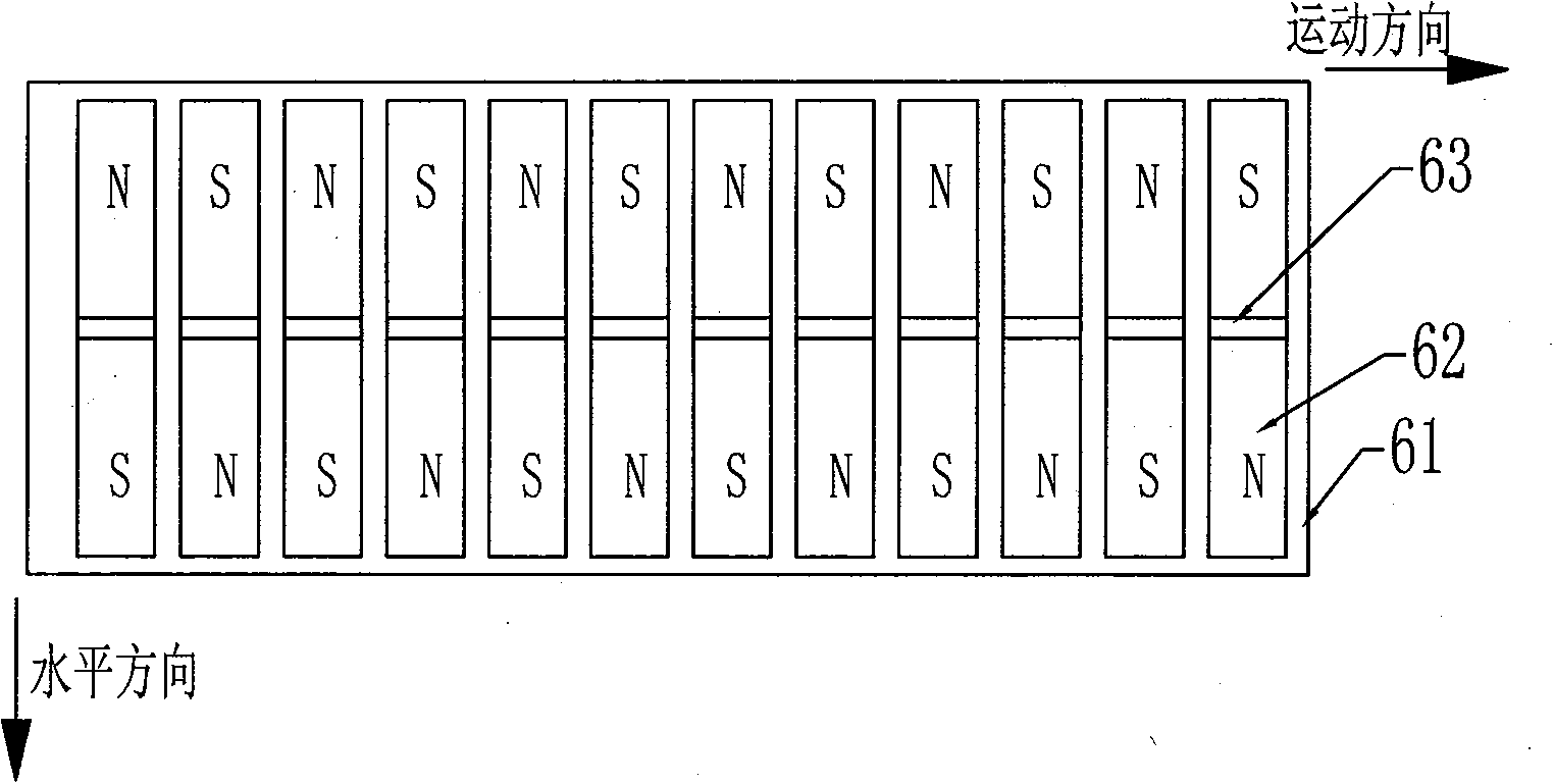
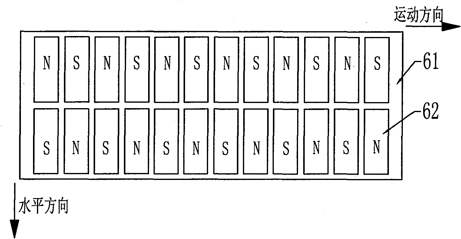
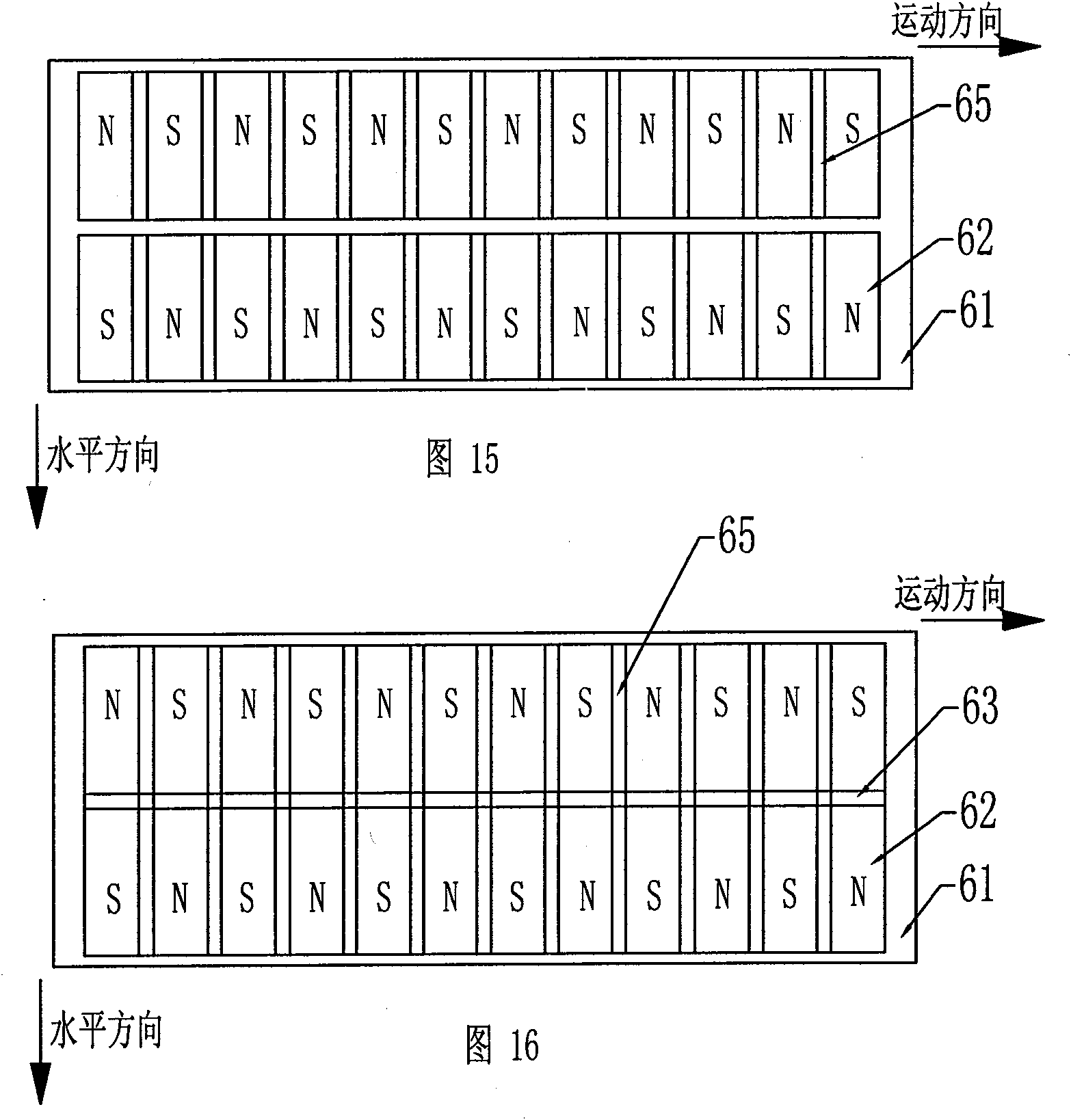
[0007] Specific implementation mode 1. Combination figure 1 and figure 2 ,as well as Figure 17 and Figure 18 Describe this embodiment, this embodiment is made up of casing 1, primary and secondary 6; Secondary 6 is made up of permanent magnet array and yoke plate 61; Primary is made up of several phase units 2; The phase unit core 3 and the phase unit winding 4 are composed; each phase unit core 3 is composed of 2k core units 5 and has a tooth hole 71, and the tooth hole 71 is composed of 2k core units 5 tooth slots 72 Formed by stacking, each core unit 5 is composed of two teeth and a yoke segment; the two teeth are arranged along the horizontal direction of the cross section, and a yoke segment is connected between the two teeth; 2k core units 5 are arranged in the casing 1 at equal intervals in sequence along the moving direction; the coil 41 is wound into a phase unit winding 4 through the tooth hole 71 of the phase unit core 3; when the motor is an m-phase motor, t...

specific Embodiment approach 2

[0008] Specific embodiment two, combine Figure 3 to Figure 6 Describe this embodiment. The first difference between this embodiment and the specific embodiment is that each core unit 5 in the phase unit core 3 is composed of a long tooth 51, a short tooth 52, a high-level yoke segment 53, a low The horizontal yoke section 54 and a vertical yoke section 55 are composed; the long teeth 51 and the short teeth 52 are arranged along the horizontal direction of the cross section, and the long teeth 51 and the short teeth 52 are sequentially connected with high The horizontal yoke section 53, the vertical yoke section 55 and the low horizontal yoke section 54, the side root of the long tooth 51 is connected to the side of one end of the high horizontal yoke section 53, and the high horizontal yoke The other side of the section 53 is connected to the root of one side of the vertical yoke section 55, and the other side of the vertical yoke section 55 is connected to one end of the low...

specific Embodiment approach 3

[0009] Specific embodiment three, combine image 3 and Figure 4 Describe this embodiment, the difference between this embodiment and the specific embodiment is that the coil 41 is wound circularly on the upper part of the long tooth 51 or on the high horizontal yoke segment 53 or the vertical yoke segment 55 through the two tooth holes 71 to form a Phase phase unit winding 4. Other compositions and connection methods are the same as those in Embodiment 1.


PUM


Abstract

The invention provides an inter-phase electromagnetic decoupling flat permanent magnet synchronous straight line motor, which relates to the motor field and solves the problems that: the magnetic coupling existed between the phases influences the control precision of the current, and a magnetic path passed by a magnetic flux generated by each phase of winding is too long to cause a large consumption of the stator iron. The primary grade of the inter-phase electromagnetic decoupling flat permanent magnet synchronous straight line motor comprises phase units, wherein each phase unit comprises phase unit iron cores and phase unit windings; each phase unit iron core composes the phase unit iron core including tooth holes with 2k iron core units; the tooth holes are formed by superposing tooth grooves; each iron core unit is composed of two teeth and a magnetic yoke section; the two teeth are arranged along a horizontal direction of the cross section; the magnetic yoke section is connected between the two teeth; the 2k iron core units are arranged in a shell at interval along a moving direction; coils are wound into the phase unit winding through the tooth holes; when the motor is the m-phase motor, im phase units are existed therein; a centre distance L between two adjacent phase unit iron cores is L=[(j-1)+1 / m]tp. The inter-phase electromagnetic decoupling flat permanent magnet synchronous straight line motor is used as the motor or a generator.

Description

technical field [0001] The invention relates to the field of motors, in particular to a flat permanent magnet linear synchronous motor. Background technique [0002] The structure of the existing flat permanent magnet linear synchronous motor is as follows: Figure 24 shown. Since there is magnetic coupling between phases, on the one hand, the existence of mutual inductance will affect the control accuracy of the current; The power consumption is large, which limits the further improvement of the motor efficiency. Contents of the invention [0003] In order to solve the problem that the magnetic coupling between the phases affects the control accuracy of the current; and the shortcoming that the magnetic flux generated by the energization of each phase winding passes through a long magnetic circuit, the iron loss of the stator is relatively large, and a new method is proposed. A flat permanent magnet synchronous linear motor with phase-to-phase electromagnetic decoupling...

Claims


Application Information

Patent Timeline
Patent Type & Authority Applications(China)
IPC IPC(8): H02K41/03
Inventor 寇宝泉谢大纲
Owner HARBIN INST OF TECH
Why Eureka
Try Eureka