
Transition method and transition joint between polar plate and copper conducting beam

A transition joint, conductive beam technology, applied in the electrolysis process, electrodes, electrolysis components, etc., can solve the problems of poor anode plate adsorption rate, large current energy consumption, and high product cost, and achieve increased output, improved production efficiency, and resistance value. small effect

Inactive Publication Date: 2010-11-17
石佐
View PDF3 Cites 2 Cited by
  • Summary
  • Abstract
  • Description
  • Claims
  • Application Information

AI Technical Summary

Problems solved by technology

Using such a transition conduction method to the anode plate, the current energy consumption is large, and the electroplating of the anode plate is relatively much smaller, so the adsorption rate of the anode plate is poor, the time in the electroplating tank is long, the productivity is low, and the product cost is too high. high

Method used


Image

  • Transition method and transition joint between polar plate and copper conducting beam
  • Transition method and transition joint between polar plate and copper conducting beam
  • Transition method and transition joint between polar plate and copper conducting beam

Examples


Embodiment Construction

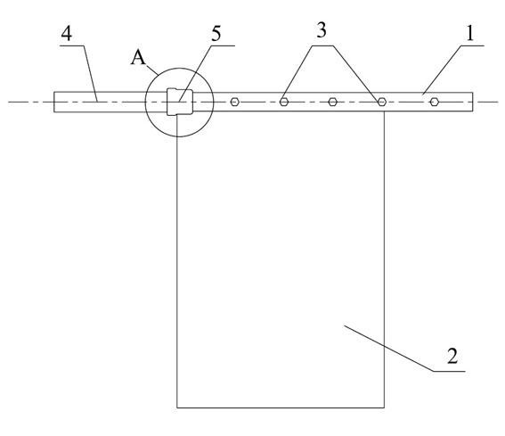
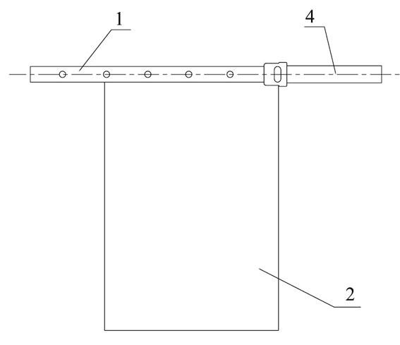
[0019] Refer to attached Figure 1-5 . The transition method between the polar plate and the copper conductive beam of the present invention is provided with a conductive beam 1, and the upper ends of the conductive beam 1 and the pole plate 2 are fixed with bolts 3, and the transition method is also provided with a mold, which is close to a section of the conductive beam 4, A section of the conductive beam 1 close to the copper conductive beam, the part of the pole plate 2 connected to the section of the conductive beam close to the copper conductive beam, and the area of ​​the pole plate close to this part are placed flat into the exothermic welded aluminum in the mold In the thermal reaction chamber, it is welded together by exothermic welding, the flux of the exothermic welding contains copper oxide, and the height of the reaction chamber is greater than the thickness of the copper conductive beam and the sum of the conductive beam and the pole plate. Thickness, the width...


PUM


Abstract

The invention provides a transition method between a polar plate and a copper conducting beam. A conducting cross beam is provided and is fixed to the upper end of the polar plate, and a mold is also provided in the method. The copper conducting beam is adjacent to one section of the conducting cross beam, the conducting cross beam is adjacent to one section of copper conducting beam, one part of the polar plate connected with the conducting cross beam adjacent to the section of the copper conducting beam and an area of the polar plate adjacent to the part are horizontally placed in a reaction chamber of the mold and are welded together by using an exothermic welding method. A welding flux of exothermic welding contains copper oxide. Because the technical scheme of the invention is adopted, the copper conducting beam, the conducting cross beam and the polar plate are fused and welded at a time, so that the connecting molecular structure of the transition joint is reconstructed, and the integrity of the transition joint is reached.

Description

technical field [0001] The invention relates to the field of electroplating, in particular to a connection transition method and a connection transition joint between a polar plate and a copper conductive beam. Background technique [0002] In the field of electroplating, such as in electrolytic copper smelting, the anode plate is made of stainless steel, and the transition method between it and the copper conductive beam is to connect the stainless steel splint type conductive beam to the copper conductive beam, and the upper end of the stainless steel anode plate is fixed and connected to the stainless steel splint type conductive beam. on the beam. The stainless steel splint-type conductive beam and the copper conductive beam are welded and connected by friction welding, and the stainless steel anode plate and the stainless steel splint-type conductive beam are welded by argon arc welding at the surface seam in addition to bolt connection. Using such a transition conduct...

Claims


Application Information

Patent Timeline
Patent Type & Authority Applications(China)
IPC IPC(8): C25C7/02C25B11/00
Inventor 石含华石佐石柱
Owner 石佐
Learn More