Automotive energy-saving emission-reducing hydraulic retarder

A hydraulic retarder, energy saving and emission reduction technology, applied in the direction of brakes, vehicle components, control devices, etc., can solve the problems of loss and failure to perfectly replace the hydraulic retarder, and achieve the effect of reducing the kinetic energy of the recovery vehicle

Inactive Publication Date: 2010-11-24
WUXI CHIMA AUTOMOBILE KINETIC ENERGY TECH DEV
View PDF9 Cites 16 Cited by
  • Summary
  • Abstract
  • Description
  • Claims
  • Application Information

AI Technical Summary

Problems solved by technology

[0003] At present, all kinds of retarders (eddy current, hydraulic, etc.) actually used at home and abroad convert the kinetic energy (or potential energy) of the car into heat energy and emit it into the air in different ways. The kinetic energy of the car depends on consuming various precious energy sources. It is a pity to lose this energy in vain.
[0004] It should be pointed out that hydraulic hybrid electric vehicles that can recover and reuse the kinetic energy of automobile braking have been initially applied in various types of urban buses, garbage trucks and express vehicles that require frequent braking and starting, and have achieved remarkable results. Energy saving and emission reduction effects, and many technical solutions, such as patent No. 87100344, ZL88214287.9, ZL200420059673.6, ZL200620040083.8, ZL200620044935.0, ZL200620044934.6, ZL200720573344.0, etc. To a certain extent, they show the role of hydraulic retarders with energy-saving and emission-reducing functions, but they cannot perfectly replace the relatively advanced hydraulic retarders currently available for more applications.

Method used


Image

  • Automotive energy-saving emission-reducing hydraulic retarder
  • Automotive energy-saving emission-reducing hydraulic retarder

Examples


Embodiment approach

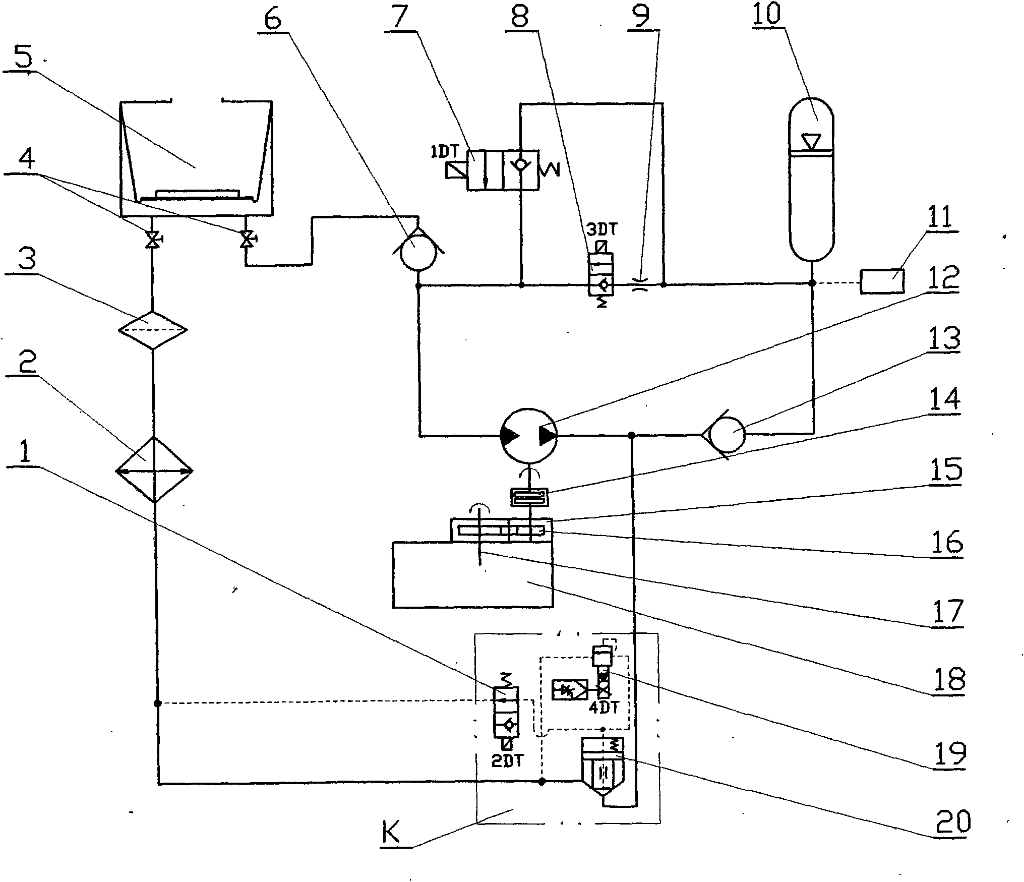
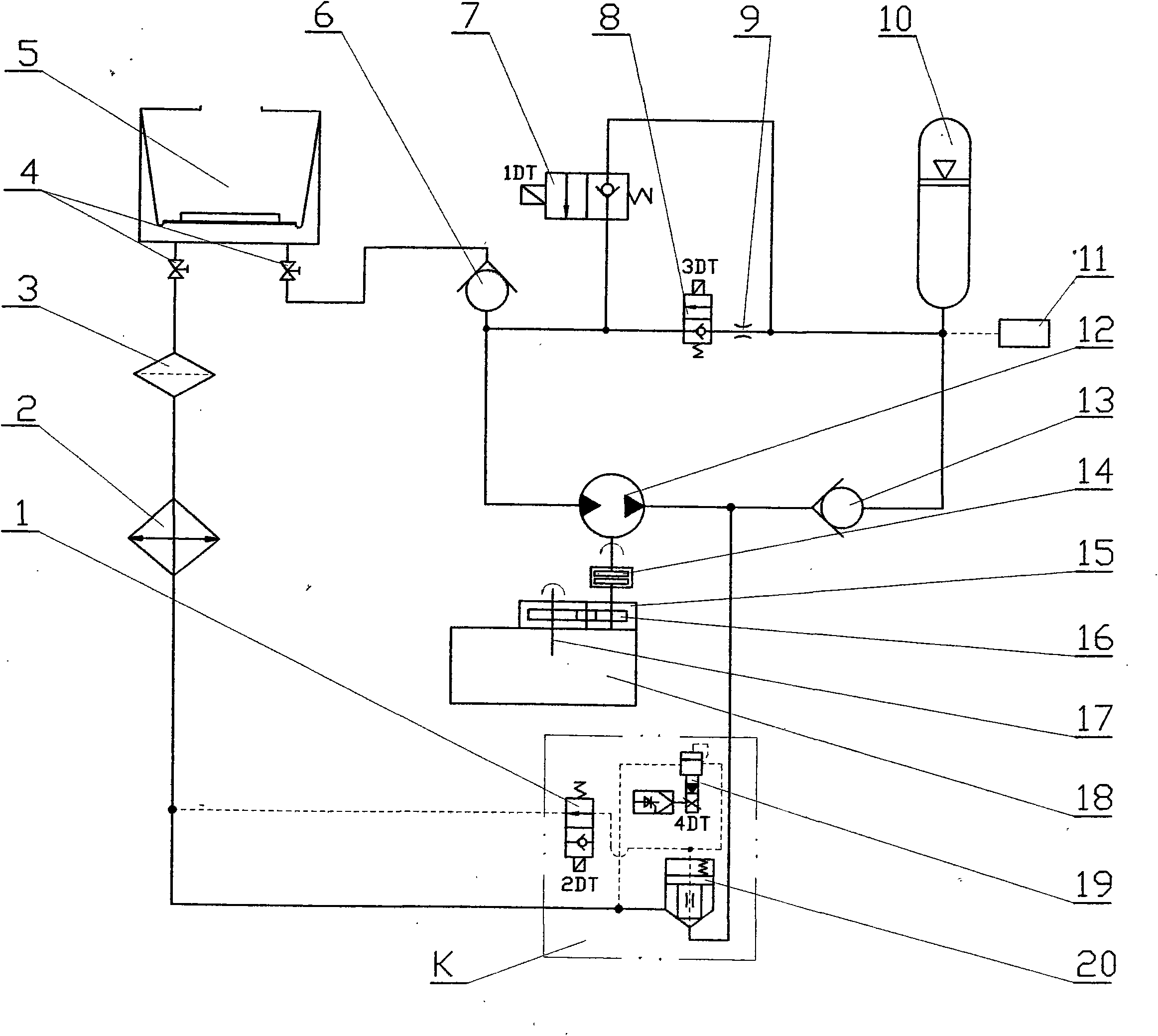
[0018] Now the automobile energy-saving and emission-reducing hydraulic retarder of the present invention will be further described in conjunction with the accompanying drawings.

[0019] See figure 1, the output end of the automobile gearbox 18 is equipped with a sub-box 15 (or a new gearbox that combines them to design one), and the oil pump / oil motor 12 is installed on the sub-box 15 by means of an electromagnetic (or pneumatic, hydraulic) clutch 14 , through a set of gears 16, connected to the output shaft 17 of the automobile gearbox 18, the inlet of the oil pump / oil motor 12 passes through the one-way valve 6 and the stop valve 4 to the diaphragm piston closed oil tank 5; the other way passes through a large two The one-position two-way electromagnetic ball valve 7 is connected to the accumulator 10, which is connected in parallel to the accumulator 10 through a small two-position two-way electromagnetic ball valve 8 and the throttle valve 9; the pressure transmitter 11 ...


PUM


Abstract

The invention relates to an automotive energy-saving emission-reducing hydraulic retarder comprising an oil pump and a hydraulic system which are mounted on an output shaft of a large or intermediate automotive transmission and connected therewith in parallel, and the automotive energy-saving emission-reducing hydraulic retarder not only has the function of the automotive hydraulic retarder, but also has the capability of recovering kinetic energy when braking an automobile and re-utilizing the kinetic energy during startup (or force application), and can further reduce the exhaust emission during the startup and realize the energy conservation and the emission reduction. The automotive energy-saving emission-reducing hydraulic retarder is characterized by being connected with the output shaft of the automotive transmission in parallel, so that the combination or the disengagement is convenient, a system can be disengaged when a fault exists, and a vehicle can still travel normally; the energy transfer during energy storage and energy release does not pass through a mechanical system of the original transmission, and the output shaft of the transmission is directly connected with a rear axle of the automobile with the help of a clutch, thereby reducing the load of the transmission; furthermore, the automotive energy-saving emission-reducing hydraulic retarder has obvious energy-saving effect, and can release the energy and apply the force during the startup of the vehicle, improve the working condition of an engine, reduce the emission of harmful gases; accelerate the starting velocity, improve the operation efficiency, change the mechanical rigid brake to the flexible hydraulic retardance, improve the riding comfort and simultaneously prolong the service life of a vehicle transmission and brake system.

Description

Technical field: [0001] The automobile energy-saving and emission-reducing hydraulic retarder of the present invention is an oil pump and a hydraulic system installed in parallel with the output shafts of large and medium-sized automobile gearboxes. It not only has the function of an automobile hydraulic retarder, but also can recycle automobiles. The kinetic energy during braking is reused during starting (or boosting), which also reduces exhaust gas emissions during starting, thereby achieving the purpose of energy saving and emission reduction. It belongs to the field of mechanical technology. Background technique: [0002] Automobile braking system is one of the most important systems in the safe driving of automobiles. With the development of engine technology and the improvement of road conditions, the driving speed of automobiles (that is, driving kinetic energy) has been greatly improved, and the traditional friction brake device is increasingly unable to meet the r...

Claims


Application Information

Patent Timeline
Patent Type & Authority Applications(China)
IPC IPC(8): B60T1/10B60K17/10
Inventor 江绍成邢科礼戴再农张顺祥崔恒生
Owner WUXI CHIMA AUTOMOBILE KINETIC ENERGY TECH DEV
Why Eureka
Try Eureka