Solid fuel fluidized bed near-zero emission hydrogen generating device

A near-zero emission, solid fuel technology, applied in hydrogen separation, hydrogen production, etc., can solve the problems of complex system control, harsh reactor and reaction conditions, etc., and achieve the effects of energy efficiency, supply, and economical utilization

Inactive Publication Date: 2010-11-24
NORTH CHINA ELECTRIC POWER UNIV (BAODING) +1
View PDF4 Cites 12 Cited by
  • Summary
  • Abstract
  • Description
  • Claims
  • Application Information

AI Technical Summary

Problems solved by technology

However, this method has strict requirements on the reactor and reaction conditions, and the system control is relatively complicated.

Method used


Image

  • Solid fuel fluidized bed near-zero emission hydrogen generating device
  • Solid fuel fluidized bed near-zero emission hydrogen generating device

Examples


Embodiment 1

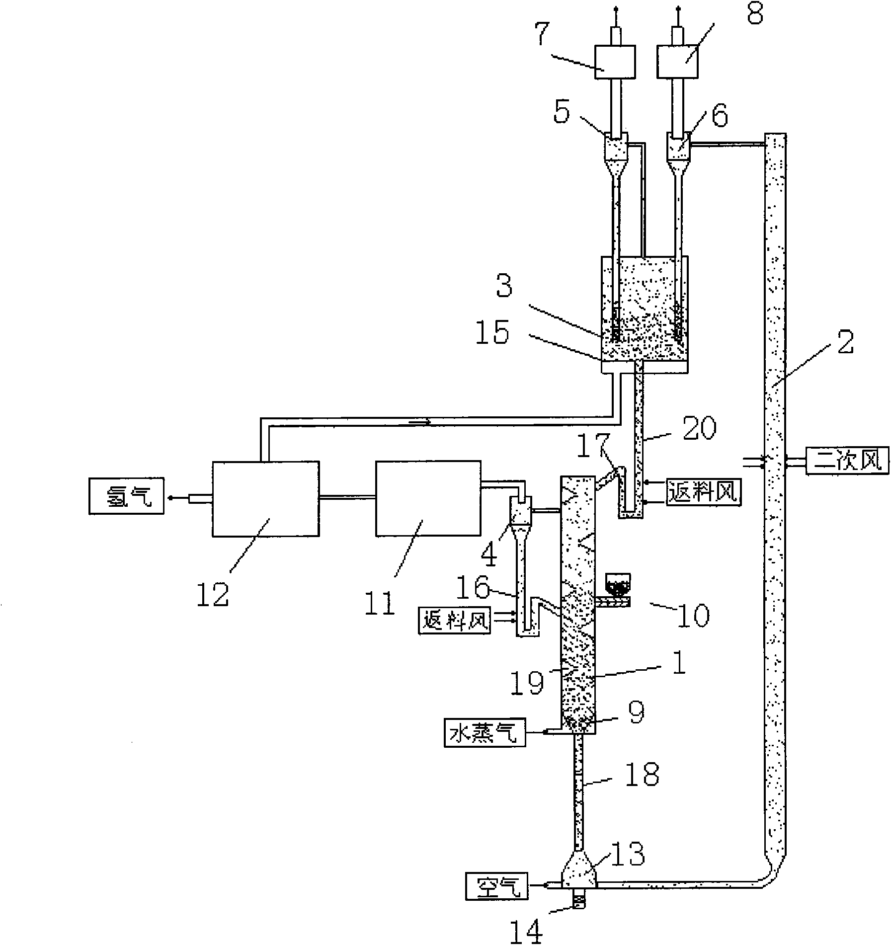
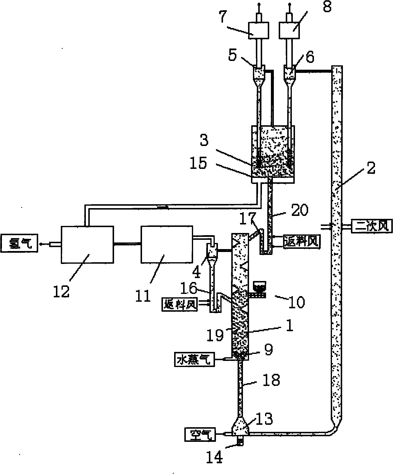
[0021] The broken coal enters the gasification reactor 1 through the feeder 10, and undergoes gasification reaction with the water vapor introduced from the bottom, and the gasification heat is fed from the Fe fuel reactor 2 3 o 4 supply. Fe just entering gasification reactor 1 3 o 4 With a higher temperature, it can also promote the conversion of gasification tar in the upper part. After the gasified gas passes through the first gas-solid separation and transposition 4, it enters the gas purification unit 11 for purification and filtration, and then enters the hydrogen separation unit 12 for separation, so as to produce relatively high-purity hydrogen. And the low-hydrogen combustible gas after separation enters in the fuel reactor 3 and Fe 2 o 3 The reaction produces CO 2 and H 2 O. CO 2 and H 2 The heat carried by O can enter the first waste heat utilization device 7, and then high-purity CO can be obtained after condensation. 2 . And the Fe after the reaction ...

Embodiment 2

[0029] The sawdust enters the gasification reactor 1 through the feeder 10 , and reacts with the water vapor fed from the bottom, and the heat of gasification is provided by the NiO fed into the fuel reactor 2 . The Ni that has just entered the gasification reactor 1 has a relatively high temperature, so it can also promote the conversion of tar in the upper part, and Ni has a certain catalytic effect, which is very beneficial to catalysis. After the gasified gas passes through the first gas-solid separation and transposition 4, it enters the gas purification unit 11 for purification and filtration, and then enters the hydrogen separation unit 12 for separation, so as to produce relatively high-purity hydrogen. The separated low-hydrogen combustible gas enters the fuel reactor 3 through the pipeline to react with NiO to generate CO 2 and H 2 O. CO 2 and H 2 The heat carried by O enters the first waste heat utilization device 7, and then high-purity CO can be obtained after...


PUM


Abstract

The invention belongs to the field of fluidized bed hydrogenation and particularly relates to a solid fuel fluidized bed near-zero emission hydrogen generating device. In the device, a raw material is fed into a gasification reactor from a feeder to be mixed and collided with a low valent metal oxide to obtain heat to be gasified in an atmosphere of vapor, the higher temperature of the low valentmetal oxide and can promote the further decomposition of gasified tar, a purification and filtration unit and a hydrogen separation unit can divide gases generated by gasification into pure hydrogen and low-hydrogen combustible gases, the low-hydrogen combustible gases are delivered to a fuel reactor through a pipe to be reacted with the metal oxide, the low valent metal oxide is oxidized in an air reactor to form oxygen, and the heat released in oxidization is released to provide heat for the system. The solid fuel fluidized bed near-zero emission hydrogen generating device ensures the circulation of a oxygen carrier among three reactors and, therefore, realizes energy and oxygen supply. High-concentration CO2 can be obtained and further used or buried deeply, so efficiency, cleanness, conservation and utilization of energy are realized.

Description

technical field [0001] The invention belongs to the field of fluidized bed hydrogen production equipment, in particular to a solid fuel fluidized bed near-zero emission hydrogen production device. Background technique [0002] In recent years, the clean and efficient utilization of energy has attracted great attention. Technologies such as gasification hydrogen production have attracted people's attention, but traditional gasification devices and methods also have great limitations. Therefore, various new devices and methods have been proposed, "A method for catalytic hydrogen production by a biomass downdraft gasifier and device thereof (200310111799.3) discloses a method for catalytic hydrogen production by a biomass downdraft gasifier , to catalyze biomass gasification to fuel gas to produce hydrogen-rich gas. However, the hydrogen production method of biomass catalytic reforming needs to find efficient catalysts and catalyst reactors, and the catalyst itself has problem...

Claims


Application Information

Patent Timeline
Patent Type & Authority Applications(China)
IPC IPC(8): C01B3/06C01B3/50
CPCY02E60/36
Inventor 董长青蒋景周陆强杨勇平张俊姣
Owner NORTH CHINA ELECTRIC POWER UNIV (BAODING)
Why Eureka
Try Eureka