Electric furnace gas purification and reclamation equipment

A technology for recovery equipment and electric furnace gas, which is applied in the field of electric furnace gas purification and recovery equipment, can solve the problems of affecting dust removal effect, high system investment, high risk factor such as leakage and explosion, and achieves enhanced sealing safety, improved safety factor, and avoiding explosions The effect of the accident

Active Publication Date: 2013-10-16
MCC CAPITAL ENGINEERING & RESEARCH
View PDF1 Cites 0 Cited by
  • Summary
  • Abstract
  • Description
  • Claims
  • Application Information

AI Technical Summary

Problems solved by technology

[0003] With the improvement of scientific and technological level, the application proportion of electric furnace in metallurgical process is getting higher and higher. At present, the relatively mature and common closed electric furnace flue gas purification methods include in-furnace combustion treatment process, wet purification process and dry purification process, etc. Among them: the combustion process in the furnace is to directly burn the gas generated in the furnace at the furnace mouth, and purify the burned gas. The whole system is relatively simple, but the gas cannot be recovered; the wet purification process is purified by wet treatment. The flue gas is then recycled to the purified gas. The process control is relatively simple, which is beneficial to eliminate unsafe factors to a certain extent, and the gas can be recovered. However, this process has the disadvantages of large floor area, high energy consumption and large water consumption; dry method Compared with the wet purification process, the purification process does not require a large amount of industrial water consumption, the system energy consumption is low, the purification efficiency is high, and the water content of the recovered gas is low. However, there are still many problems to be solved in the dry purification process, such as , the system investment is relatively high, the operation is not stable enough, the risk factor such as leakage and explosion is high, and the air flow seriously damages the interior of the dust collector, which affects the dust removal effect and accelerates the aging of the interior of the equipment. The current related equipment cannot properly solve the above problems. The problem, to be precise, is that there are very few technical equipments in related fields, and it can be said that they are at the level of a technical blank
[0004] For example, the patent case of China Patent Application No. 200910024958.3 proposes a "converter gas full-dry purification and waste heat utilization equipment and method". It is sent to the gravity dust collector for dust removal, and then passed through the post-combustion waste heat boiler, bag filter and induced draft fan in turn, and finally sent to the gas cabinet. First of all, this technical solution is suitable for converter smelting and electric furnace smelting technical fields It can only be said to be relatively close. For electric furnace smelting, its cooling and dust removal steps and the effects it can achieve cannot meet the relevant requirements, and cannot fill the above-mentioned technical gap; The dust contained in the dust collector will damage the dust collector and make it aging; moreover, the whole process does not take into account the danger of gas leakage or combustion explosion, and does not fully consider the sealing in the details. Safety in the dust removal process, but for different working conditions or emergencies, there is no corresponding structure designed to avoid gas leakage or even backflow, explosion, etc.

Method used


Image

  • Electric furnace gas purification and reclamation equipment
  • Electric furnace gas purification and reclamation equipment
  • Electric furnace gas purification and reclamation equipment

Examples


Embodiment Construction

[0065] In order to have a clearer understanding of the technical features, purposes and effects of the present invention, the specific implementation of the present invention will now be described with reference to the accompanying drawings, but those skilled in the art should understand that this is not a limitation.

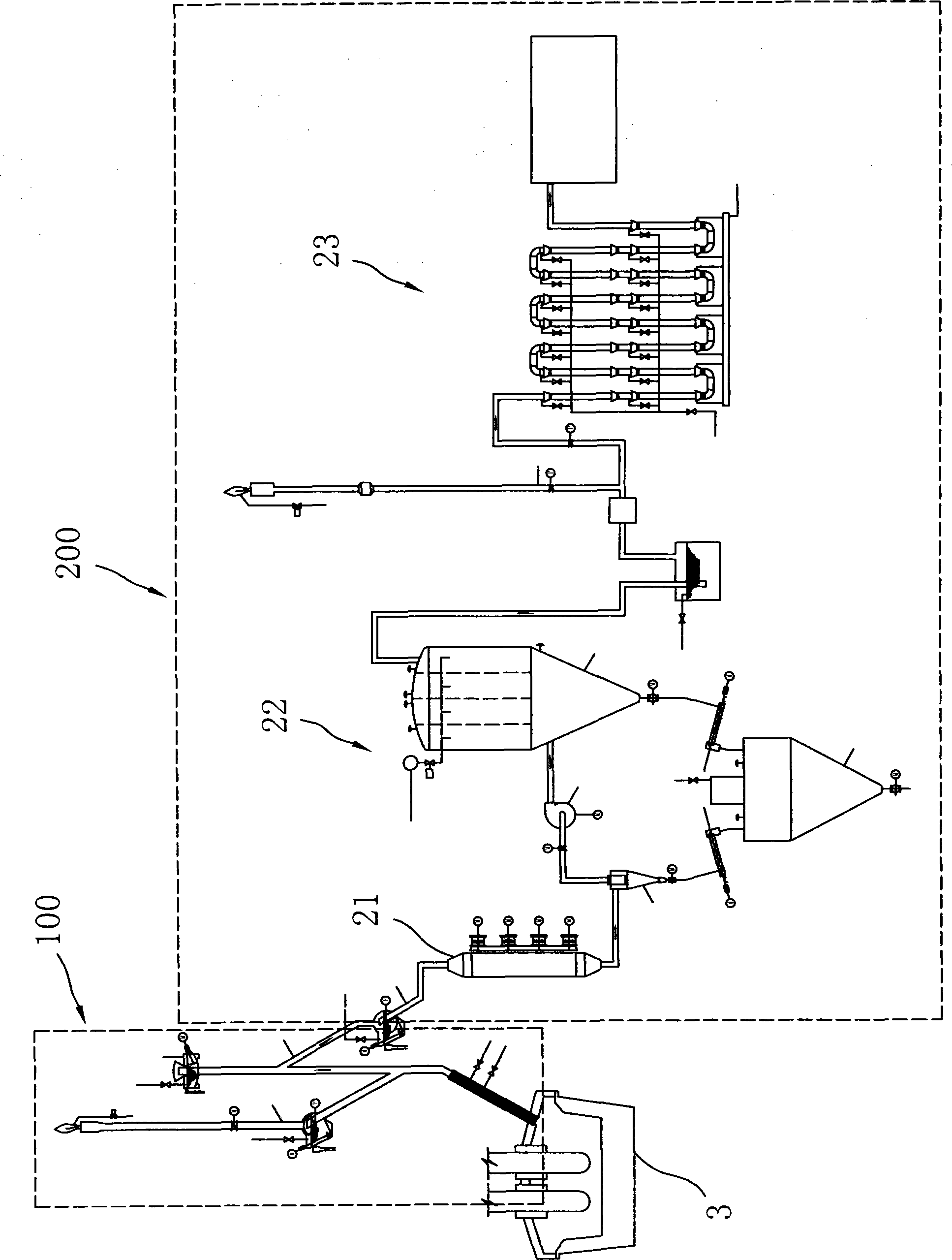
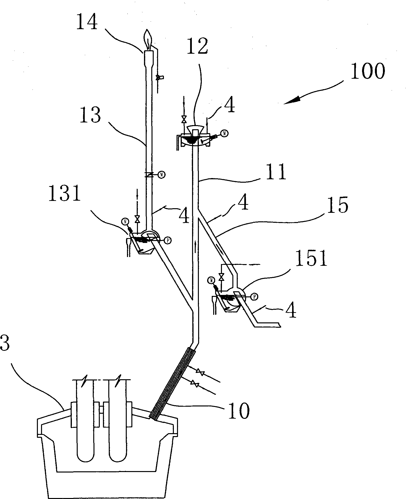
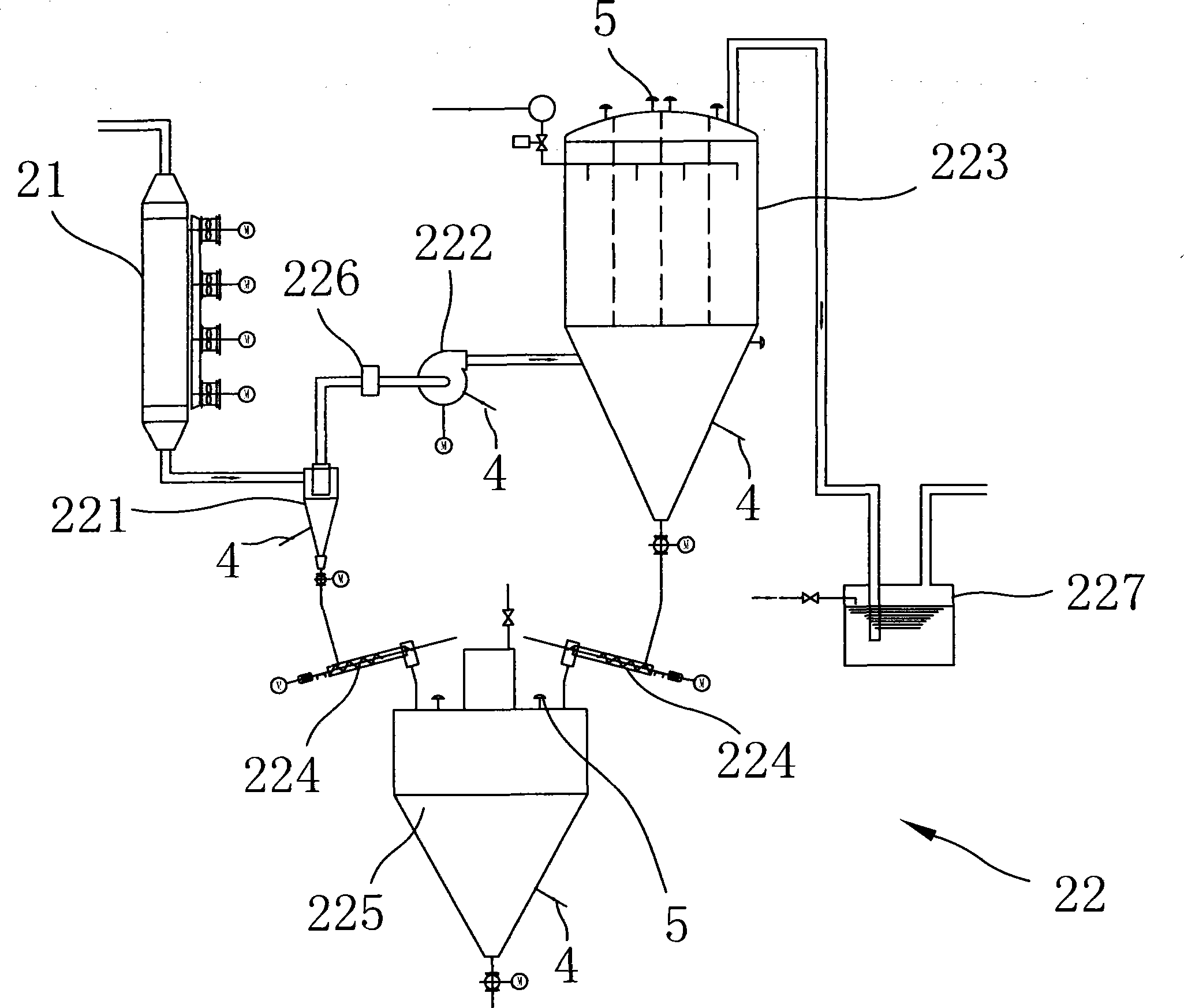
[0066] Please refer to figure 1 , is a schematic diagram of the overall structure of the electric furnace gas purification and recovery equipment of the present invention. As shown in the figure, the electric furnace gas purification and recovery equipment of the present invention mainly includes a raw gas part 100 and a clean gas part 200, wherein the raw gas part 100 is mainly used for combustion treatment and discharge The raw gas produced by the electric furnace, the clean gas part 200 is mainly used to purify the furnace gas and recover the clean gas. The raw gas part 100 is directly connected to the electric furnace, and the clean gas part 200 is connected...


PUM


Abstract

The invention discloses electric furnace gas purification and reclamation equipment, which comprises a crude gas part and a purified gas part, wherein the crude gas part can combust and discharge crude gas generated by an electric furnace and is connected with the electric furnace; the purified gas part is connected with the crude gas part and used for purifying and reclaiming the furnace gas; the purified gas part comprises a cooling device, a purification and dust removal device and a reclamation device, wherein the input end of the cooling device is connected with the crude gas part, and the cooling device is used for cooling the high-temperature furnace gas; the input end of the purification and dust removal device is connected with the output end of the cooling device, and the purification and dust removal device is used for filtering the furnace gas; and the input end of the reclamation device is connected with the output end of the purification and dust removal device, and the reclamation device is used for reclaiming the qualified gas and combusting the unqualified gas. The electric furnace gas purification and reclamation equipment can realize efficient safe purification and reclamation of the electric furnace gas, and meanwhile has the advantages of saved investment, low energy consumption, low water consumption, small floor area and the like.

Description

technical field [0001] The invention relates to the purification and recovery of electric furnace gas, in particular to an electric furnace gas purification and recovery equipment. Background technique [0002] During the generation of metal smelting, a large amount of furnace gas containing carbon monoxide, commonly known as coal gas, will be produced. Because the temperature in the metal smelting process is very high, the accompanying furnace gas is also a gas with very high temperature. For example, The temperature of the furnace gas produced by the converter during the blowing period is about 1600 degrees Celsius, and the furnace gas generated during the new electric furnace smelting process is also as high as about 600 degrees Celsius. There are a lot of dust and impurities, so the recycling of furnace gas is difficult. On the one hand, the high concentration of carbon monoxide makes the high-temperature furnace gas flammable and explosive, so the requirements for seali...

Claims


Application Information

Patent Timeline
Patent Type & Authority Patents(China)
IPC IPC(8): C10K1/02F27D17/00
CPCY02P10/25
Inventor 赵楠刘红娟瞿华刘革鲁亮李巍杨永符宁郝景章王世芹柴凤飞
Owner MCC CAPITAL ENGINEERING & RESEARCH
Why Eureka
Try Eureka