
External passive cooling method and device thereof

A passive, water-cooling device technology, applied in natural cooling systems, door/window protection devices, energy-saving heating/cooling, etc., can solve the problems of indoor area temperature rise, high indoor area temperature, low cost, etc. load, heat load reduction, low cost effect

Active Publication Date: 2012-09-05
于向阳
View PDF0 Cites 0 Cited by
  • Summary
  • Abstract
  • Description
  • Claims
  • Application Information

AI Technical Summary

Problems solved by technology

[0015] The invention provides a method and device with external passive cooling, which overcomes the deficiencies of the prior art and effectively solves the problem of high temperature in the indoor area caused by the high heat gain of solar radiation caused by light-transmitting enclosure structures such as windows It can effectively and greatly reduce the temperature rise of indoor areas caused by light-transmitting enclosure structures such as windows, and the cost is low, and it is easy to cooperate with buildings

Method used


Image

  • External passive cooling method and device thereof
  • External passive cooling method and device thereof
  • External passive cooling method and device thereof

Examples


Embodiment 1

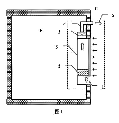
[0062] as attached figure 1 As shown, the device with external passive cooling includes an indoor area B and an external passive cooling device C, and the device C with external passive cooling includes an inner sunshade facility 6 and a light-transmitting enclosure structure, and the inner sunshade facility 6 itself or light-transmitting No less than one layer of airflow channel formed between the permanent enclosure structure itself or the inner sunshade facility 6 and the light-transmitting enclosure structure is an exhaust cavity, and the exhaust cavity has an air inlet and an exhaust; the cooling unit a is located in the indoor area or outside the indoor area, or the evaporative cooling unit a is located at the top of the light-transmitting enclosure or / and at the bottom of the light-transmitting envelope or / and at the side of the light-transmitting envelope, or The evaporative refrigeration device a is located at a place where it can be placed; the evaporative refrigerat...

Embodiment 2

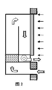
[0068] as attached figure 1 and 2 As shown, the difference between embodiment 2 and embodiment 1 is that the exhaust cavity of embodiment 2 has no less than two layers and is S-shaped, and the exhaust cavity has an air inlet and an exhaust place.

Embodiment 3

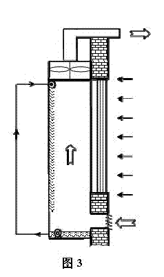
[0070] as attached Figures 1 to 3 Shown, the difference between embodiment 3 and embodiment 1 and 2 is: as attached image 3 As shown, there is no less than one layer of open-type wet curtain water film device on the inner wall of the exhaust cavity of embodiment 3, and the air that flows through the exhaust cavity can be combined with the water film of the open-type wet curtain water film device. In contact with each other; the open wet curtain water film device includes a nozzle, a water pump and a water receiving tank. The water pump sends the water in the tank to the nozzle through the water pipe, and the water sprayed by the nozzle forms a water film and falls into the water receiving tank. The open wet curtain water film device is a single layer. The expanded water film is the heat and moisture exchange medium of air flow and water. Unlike the filler, the water film itself forms a cold barrier while heat and moisture exchange occurs to form cold air through convective ...


PUM


Abstract

The invention relates to a method using external passive cooling and a device thereof. The method is carried out as follows: after being processed by an evaporative refrigeration device and passing through the air exhaust cavity of an external passive cooling device, air outside an indoor area is discharged out from the indoor area. The invention is suitable for various home buildings, public buildings and industrial buildings, and substantially absorbs the obtained solar radiation thermal quantity of a transparent building envelope in a passive cooling mode, thereby effectively reducing indoor obtained thermal load, being easy to be matched with architectural space and having lower cost; and especially the application thereof in dry and hot areas aims at the efficient graded application of dry air energy, effectively reduces the obtained thermal load of transparent building envelopes such as windows and the like and realizes more effective graded configuration of energy.

Description

Technical field [0001] The invention relates to the technical field of heating, ventilating and air conditioning, and is a method and device with external passive cooling, which is applicable to various residential, public buildings and industrial buildings, so as to effectively reduce the solar radiation heat gain of the light-transmitting enclosure structure of the room . technical background [0002] The "Design Standards for Energy Conservation of Public Buildings" promulgated and implemented by China in 2005 pointed out that China's building energy consumption has exceeded 1 / 4 of the country's total energy consumption, and will gradually increase to more than 1 / 3 with the improvement of people's living standards. In building energy consumption, HVAC energy consumption accounts for about 27.4%. Therefore, vigorously advocating HVAC energy conservation plays a vital role in building a resource-saving, environment-friendly, low-carbon society. [0003] The cooling load bo...

Claims


Application Information

Patent Timeline
Patent Type & Authority Patents(China)
IPC IPC(8): E06B9/24E06B9/264E06B7/00F24F12/00F24F1/0071
CPCY02B10/20Y02B10/24E04B1/74F24F2001/0092Y02B30/545F24F5/0035F24F5/0046Y02A30/272F24F1/0007Y02B30/54Y02P80/20F24F1/0071
Inventor 于向阳
Owner 于向阳
Learn More