Double-Cuk buck-boost output parallel-type converter

A buck-boost and inverter technology, which is applied to output power conversion devices, AC power input conversion to DC power output, electrical components, etc., can solve problems such as increasing system costs and affecting conversion efficiency, and achieves a simple control scheme , fast dynamic response, and the effect of reducing EMI

Inactive Publication Date: 2010-11-24
YANSHAN UNIV
View PDF1 Cites 21 Cited by
  • Summary
  • Abstract
  • Description
  • Claims
  • Application Information

AI Technical Summary

Problems solved by technology

The other is the isolation solution, that is, adding a step-up transformer to the converter to increase the voltage level and achieve electrical isolation, but the addition of the transformer will also increase the system cost and affect the overall conversion efficiency

Method used


Image

  • Double-Cuk buck-boost output parallel-type converter
  • Double-Cuk buck-boost output parallel-type converter
  • Double-Cuk buck-boost output parallel-type converter

Examples


Embodiment Construction

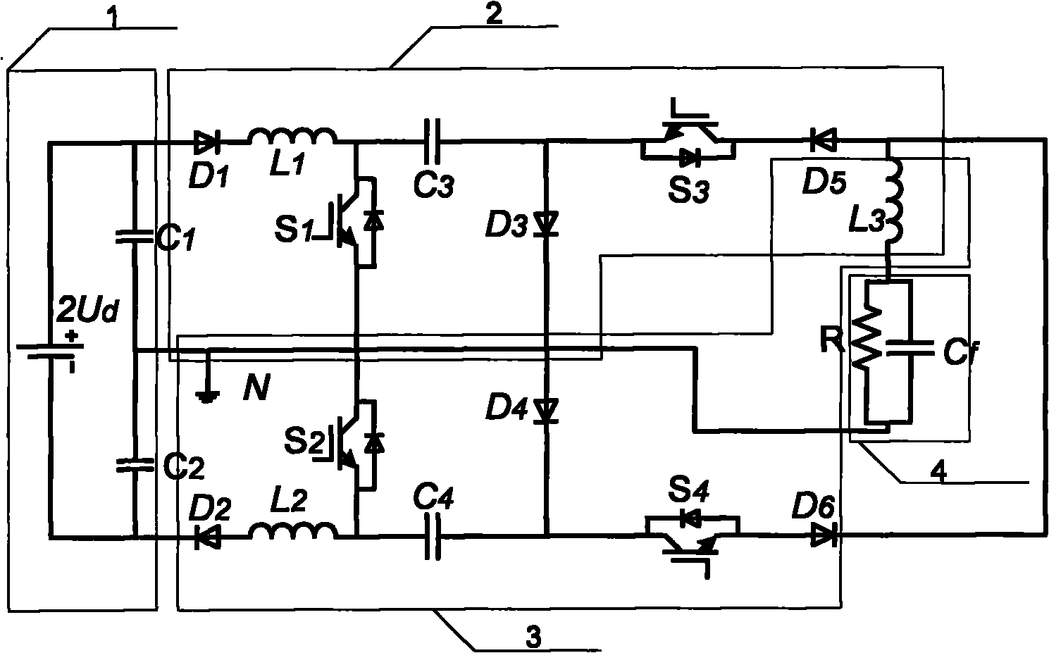
[0022] as attached figure 1 As shown, the dual Cuk buck-boost output parallel inverter of this embodiment includes a capacitor voltage divider circuit 1, a first Cuk circuit 2 and a second Cuk circuit 3, and the capacitor voltage divider circuit 1 is composed of two serially connected first Cuk circuits A capacitor C1 and a second capacitor C2 are formed, the series connection point of the first capacitor C1 and the second capacitor C2 is connected to the zero potential point, the other end of the first capacitor C1 is connected to the distance pole of the external power supply, and the other end of the second capacitor C2 is connected to the external power supply In the first Cuk circuit 2, the anode of the first power diode D1 is connected to the positive pole of the power supply, the cathode is connected to one end of the first inductance L1, and the other end is connected to the anode S1 of the first power switch tube and one end of the third capacitor C3. The cathode of a...


PUM


Abstract

The invention discloses a double-Cuk buck-boost output parallel-type converter which is formed by connecting two Cuk-type DC / DC (direct current / direct current) converters capable of achieving the buck-boost output at the output in parallel, and can achieve the DC / AC (direct current / alternating current) single-phase conversion and further achieve the three-phase conversion through expansion. The converter has the following basic functions: the double-Cuk buck-boost output parallel-type converter can achieve the buck-boost conversion and normally serve the function of conversion even if the inputted DC voltage is lower or the variation range of the DC voltage is wider; the problem that the bridge arms are directly connected is avoided in the entire circuit, thus ensuring the high reliability; the follow current is not allowed to pass through the body diode of a switching tube, but flows through an independent diode, so that a power switching tube and a power diode can be respectively subject to optimized design; the design of circuit parameters, which is based on the method for designing a DC Cuk converter, is simple; and the inductive current runs in a continuous state, thus reducing the EMI (electro-magnetic interference). The invention is mainly applicable to the fields of photovoltaic generation, fuel-cell power generation and other power generation based on renewable energy and new energy, in which the level of operating voltage is lower or the variation range thereof is wider.

Description

technical field [0001] The invention relates to an inverter in an electric energy conversion device, in particular to single-phase or multi-phase inverter application occasions capable of stepping up or stepping down voltage. Background technique [0002] Renewable energy and new energy power generation technology is the core technology to cope with the energy crisis, maintain sustainable development, and realize a "low-carbon" economy. Inverters are key components in renewable and new energy power generation systems. Compared with traditional energy sources, renewable energy and new energy power generation devices are characterized by the fluctuation and randomness of their output power. The specific performance is that the DC voltage provided by them has a relatively wide range of variation. Specific to photovoltaic arrays, fuel cells and small wind turbines, they also have the characteristics of relatively low output voltage levels. The traditional inverter is a buck-ty...

Claims


Application Information

Patent Timeline
Patent Type & Authority Applications(China)
IPC IPC(8): H02M7/497H02M1/12
Inventor 王立乔王欣邬伟扬
Owner YANSHAN UNIV
Why Eureka
Try Eureka