Flow channel switching valve

A technology of flow path switching and flow port, which is applied in the direction of multi-way valves, valve devices, valve details, etc., can solve the problems of damaging rotor rotation, aggravated cross-contamination, and generation of cutting chips, so as to improve sliding performance and prevent Effects of cross-contamination and wear reduction

Inactive Publication Date: 2010-11-24
SHIMADZU SEISAKUSHO CO LTD
View PDF3 Cites 17 Cited by
  • Summary
  • Abstract
  • Description
  • Claims
  • Application Information

AI Technical Summary

Problems solved by technology

[0004] If the flow path switching valve is used for a long time, the sliding surface of the rotor (resin), which is softer than the stator (ceramic), will wear out, causing problems such as increased torque of the valve, fluid leakage, Exacerbation of cross contamination caused by liquids, etc.
If the rotor is rotated in this state, if the material of the rotor is resin, the surface of the stator and the rotor will be cut due to rotational friction, resulting in chipping and deterioration of the subsequent string
On the other hand, when the material of the rotor is made of ceramics, such cutting chips will not be generated, but the surface roughness of the contact surface between the stator and the rotor must be reduced in consideration of sealing performance, and the flatness must also be as high as High precision, if such surfaces are pressed against each other strongly, there will be a phenomenon of mirror adhesion called so-called linking, which will impair the rotational movement of the rotor.

Method used


Image

  • Flow channel switching valve
  • Flow channel switching valve
  • Flow channel switching valve

Examples


Embodiment Construction

[0029] Hereinafter, embodiments of the present invention will be described with reference to the drawings.

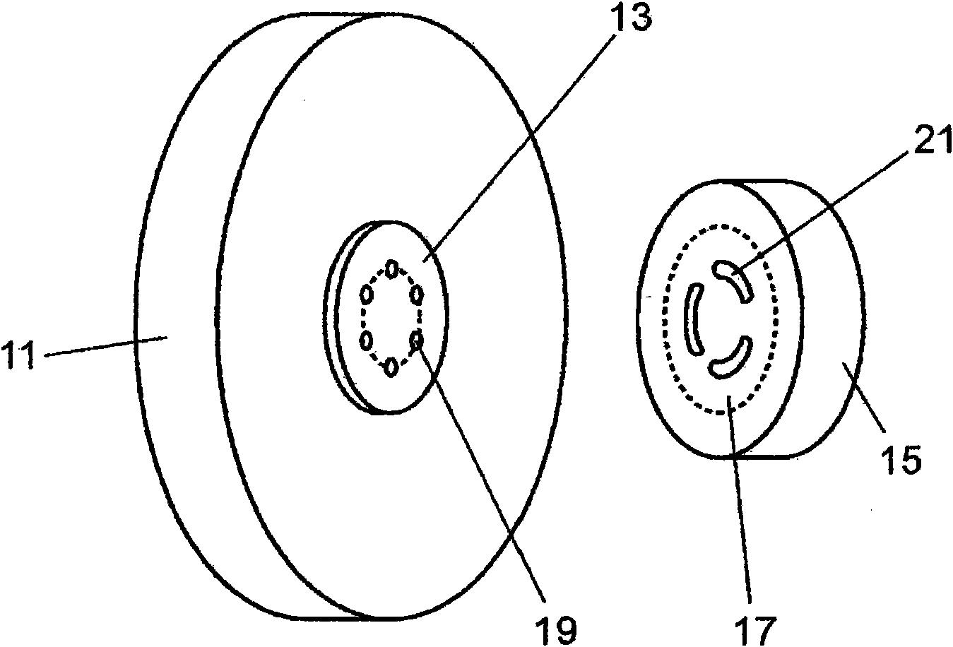
[0030] figure 1 It is a schematic perspective view of the stator and the rotor part of the channel switching valve of one embodiment.

[0031] The stator 11 is made of stainless steel, and is integrally formed with a housing connected to a flow path. The stator sliding surface 13 of the stator 11 is in contact with the rotor sliding surface 17 of the rotor 15 , and the through hole 19 provided on the stator 11 is in communication with the groove 21 provided on the rotor 15 . The rotor 15 is made of resin such as PEEK, and is provided with a plurality of arc-shaped grooves 21 .

[0032] In order to improve sliding properties, it is preferable to grind (mirror finish) the stator sliding surface 13 of the stainless steel stator 11 using diamond abrasive grains (grain diameter: 1 to 3 μm).

[0033] A DLC coating with a thickness of about 2 μm is formed on the sliding su...


PUM


Abstract

In order to enhance the durability of a rotor, provided is a flow channel switching valve which has a stator (11) with contact face (13) and a rotor (15) with contact face (17). The stator (11) on the contact face (13) has throughflow holes (19) to be connected to multiple flow channels, respectively. The rotor (15) has at least one groove (21) for communication between two of the throughflow holes (19) of the stator (11). The rotor is urged against the contact face (13) of the stator (11) and makes rotational slide so as to attain switching of the throughflow holes (19) of the stator (11) to be brought into communication. The contact face (13) of the stator (11) results from application of DLC coating and subsequent polishing processing. On the other hand, the contact face (17) of the rotor (15) consists of a resin.

Description

technical field [0001] The invention relates to a flow path switching valve used in analytical devices such as high performance liquid chromatography. Background technique [0002] In order to select a solution such as a sample or a solvent, or to introduce a sample into the analysis system from the outside, the analysis device is equipped with a mechanism for switching the flow path. For example, in a high-performance liquid chromatograph, there is a mechanism for switching the mobile phase flow path that transports liquid under high pressure (tens of MPa) to introduce the sample solution under atmospheric pressure into this flow path, and this mechanism has flow switching valve. [0003] Previously, the flow path switching valve for this application used the following flow path switching valve (for example, Patent Document 1), which can make a disc-shaped rotor with a switching groove formed on one side and a through hole formed with the groove. The disc-shaped stator is...

Claims


Application Information

Patent Timeline
Patent Type & Authority Applications(China)
IPC IPC(8): F16K3/08F16K11/074
CPCF16K11/0743F16K25/005G01N2030/202
Inventor 保永研壱
Owner SHIMADZU SEISAKUSHO CO LTD
Why Eureka
Try Eureka