Coal injection system of blast furnace

A technology of blast furnace coal injection and tank injection, which is applied to blast furnaces, blast furnace details, blast furnace parts, etc., can solve problems such as lagging of injection rates, delays, and damage to furnace conditions, so as to prevent lags and large fluctuations, and enhance self-efficacy. Adaptability, the effect of avoiding large fluctuations

Inactive Publication Date: 2010-12-01
WISDRI ENG & RES INC LTD
View PDF2 Cites 23 Cited by
  • Summary
  • Abstract
  • Description
  • Claims
  • Application Information

AI Technical Summary

Problems solved by technology

In general, the control of the injection rate is to rely on manual experience or a semi-automatic method to fix the delivery gas flow rate, and then compare the actual injection volume with the set injection volume, and use the proportional integral derivative (PID) algorithm to control the tank pressure. , and the control of the tank pressure is realized by adjusting the amount of air supplement. For this adjustment method, when the coal injection rate deviates from the set value, the control program will automatically increase or decrease the set value of the tank pressure. The air regulating valve will be adjusted according to the deviation between the actual value of the tank pressure and the set value. Since it is a relatively slow process to change the tank pressure through the amount of air supply, and because there is no online detection instrument for the injection rate, the calculation of the injection rate is lagging behind. Therefore, it is a huge lag process fo

Method used


Image

  • Coal injection system of blast furnace
  • Coal injection system of blast furnace
  • Coal injection system of blast furnace

Examples


Embodiment Construction

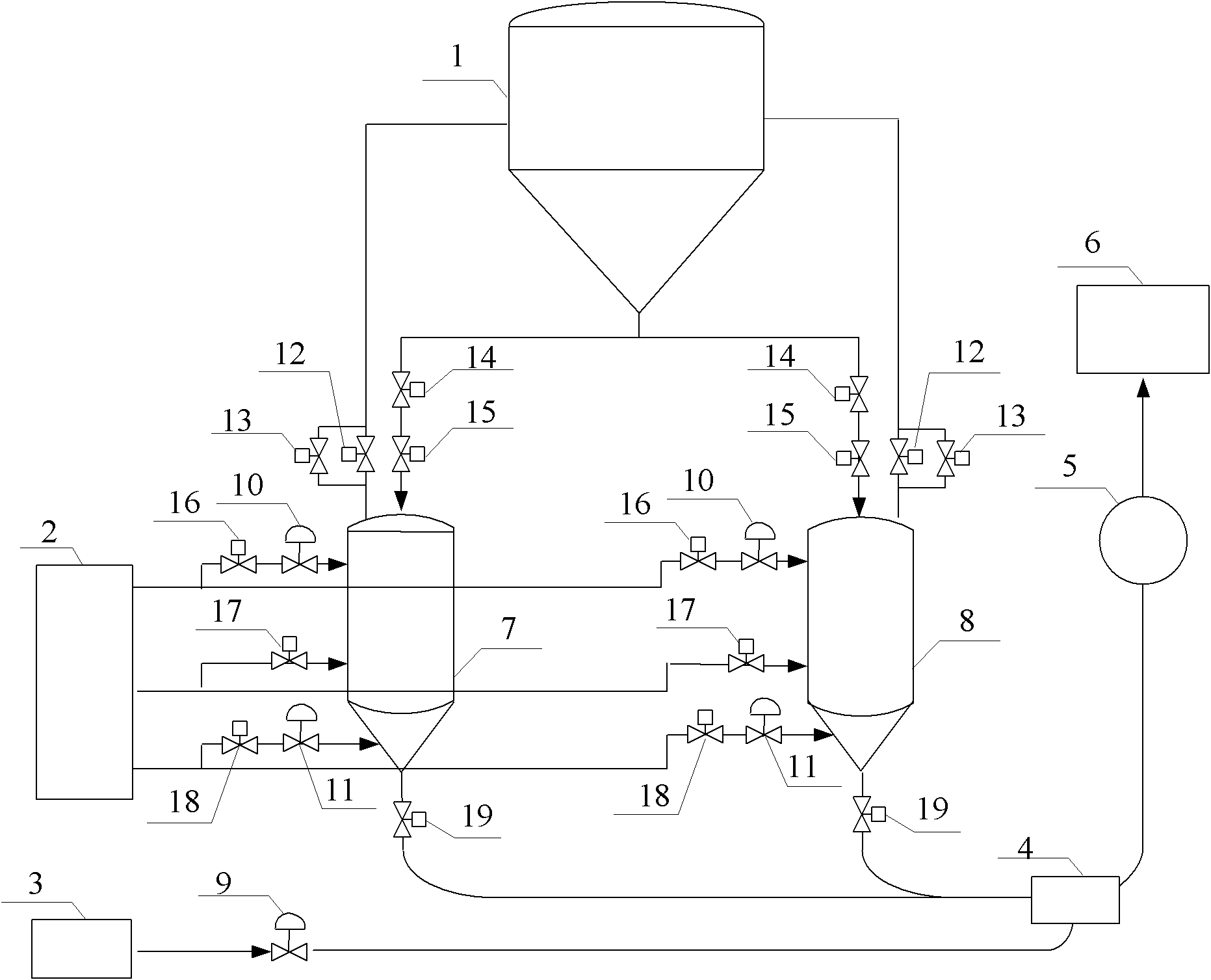
[0021] The blast furnace coal injection injection system provided by the present invention can realize the control of the blast furnace coal injection injection rate, and the system includes a nitrogen pressure regulating station 2, an air compressor station 3, a mixer 4, a distributor 5, and multiple injection tanks , Shut-off valve and regulating valve.

[0022] The structure of the blast furnace coal injection injection system will be described below by taking the two-tank parallel injection mode as an example.

[0023] Such as figure 1 As shown, the blast furnace coal injection injection system is provided with a first injection tank 7 and a second injection tank 8, which are respectively connected to the pulverized coal bin 1 through pipelines, a charging shut-off valve 14, and a blanking shut-off valve 15. Fill the blowing tank, and at the same time connect with the pulverized coal bin 1 through the pipeline, the small release shut-off valve 12, and the large release sh...


PUM


Abstract

The invention relates to a coal injection system of a blast furnace, which comprises a plurality of injection tanks, wherein the upper parts of the injection tanks are connected with a coal powder bin (1) through pipelines, charging dump valves (14) and blanking dump valves (15) for injection of materials in the tanks, and are respectively connected with the coal powder bin through pipelines, small bleeding dump valves (12) and large bleeding dump valves (13) for bleeding of the injection tanks at the same time; the middle parts of the injection tanks are respectively connected with a nitrogen pressure regulating station (2) through three connecting pipelines and valves in three ways, wherein one way is used for pressure complement of the injection tanks, one way is used for pressure recharging of the injection tanks, and the last way is used for fluidizing the coal powder in the injection tanks; and the lower parts of the injection tanks are respectively connected with a mixer (4) through pipelines and coal injection dump valves (19), and the mixer is connected with a dispenser (5) and each blast hole of a blast furnace (6) through pipelines. The invention can effectively prevent interference of furnace pressure fluctuation on the injection rate, prevent lagging and large fluctuation in the process of tank pressure regulation and ensure the fast, stable and uniform regulation of tank pressure.

Description

technical field [0001] The invention relates to the technical field of blast furnace automatic control, in particular to a blast furnace coal injection system. Background technique [0002] Blast furnace coal injection technology is the central link of blast furnace system structure optimization, which has the advantages of greatly reducing the coke ratio, improving economic benefits, and reducing environmental pollution. Coal injection technology, as a major trend in the development of blast furnace ironmaking technology at home and abroad, is one of the three important technical routes for the development of my country's iron and steel industry. With the development of coal injection technology in the direction of high injection rate dense phase transportation, how to adjust the amount of pulverized coal injection stably, uniformly and accurately is an important basis for maintaining stable furnace temperature, ensuring smooth furnace conditions, and making the blast furna...

Claims


Application Information

Patent Timeline
IPC IPC(8): C21B7/00F27D3/18
Inventor 李泽辉强健闫朝付
Owner WISDRI ENG & RES INC LTD
Why Eureka
Try Eureka