
Swing type hydraulic proportioning and servo valve

A swing type, servo valve technology, applied in the field of hydraulic components, can solve the problems of large minimum unit value of feedback angle, low control accuracy, reduced control accuracy, etc., to achieve accurate output flow and pressure, convenient and flexible operation, and control. high precision effect

Inactive Publication Date: 2010-12-01
山东通亚机械有限公司
View PDF8 Cites 8 Cited by
  • Summary
  • Abstract
  • Description
  • Claims
  • Application Information

AI Technical Summary

Problems solved by technology

Since the DC brushless motor needs a three-phase bridge power amplifier circuit, the winding adopts a star or delta connection, and the symmetrical two phases cannot be energized at the same time, so it is easy to generate vibration at the balance position, resulting in unstable working performance of the valve.
The existing built-in angle position sensors are divided into potentiometers, synchros, resolvers and photoelectric encoders. The error range of potentiometers and synchros is about 1°, and the influence of resolver errors makes the control accuracy greatly Reduced; the photoelectric encoder may produce dead zone angle and non-single value error, the minimum unit value of the feedback angle is large, the feedback angle value is discrete, and the control accuracy is difficult to improve
Moreover, it is necessary to process a specific drum-shaped opening valve sleeve, which increases the difficulty of assembly and increases the production cost
Another example is a digital hydraulic servo rotary valve (Patent No. 86107688) and a digital direct control servo valve (Patent No. 98201967). The minimum step angle of the motor is about 0.36 degrees, and the control accuracy is not high
Since the stepper motor can only rotate the step angle at a time, the hydraulically controlled equipment cannot be guaranteed to stop at the set position
When the valve core rotates to near the zero position, the valve port cannot be completely closed, which will cause pressure oil to leak into the working chamber

Method used


Image

  • Swing type hydraulic proportioning and servo valve
  • Swing type hydraulic proportioning and servo valve
  • Swing type hydraulic proportioning and servo valve

Examples


Embodiment Construction

[0033] Embodiments of the present invention will be further described below in conjunction with the accompanying drawings.

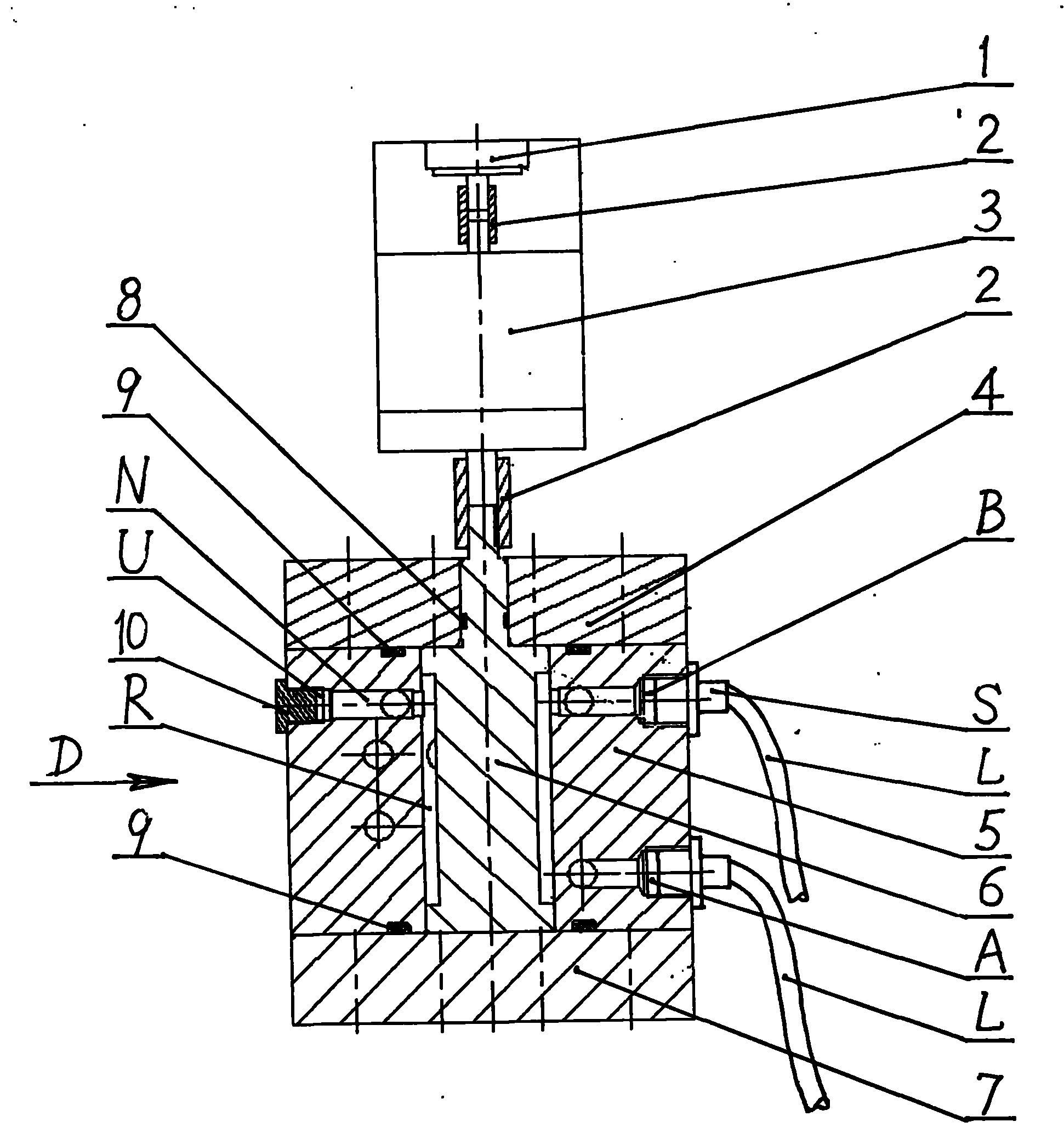
[0034] refer to figure 1 The output shaft at the outer end of the swing motor 3 is connected to the central axis of the angular displacement sensor 1 through the coupling 2, the output shaft at the inner end is connected to the connecting shaft of the spool 6 through the coupling 2, and the spool 6 is installed at the center of the valve body 5 In the valve hole R, the top valve cover 4 and the bottom valve seat 7 close the valve hole R. The back of the valve seat 7 has an ascending oil hole A and a descending oil hole B, which are connected to the oil delivery pipe L through a pipe joint S, and the process hole U opened on the vertical surface of the valve seat 7 is blocked by a screw plug 10 to prevent oil leakage. Valve cover 4 and valve seat 7 are connected and fixed with valve body 5 by bolts.

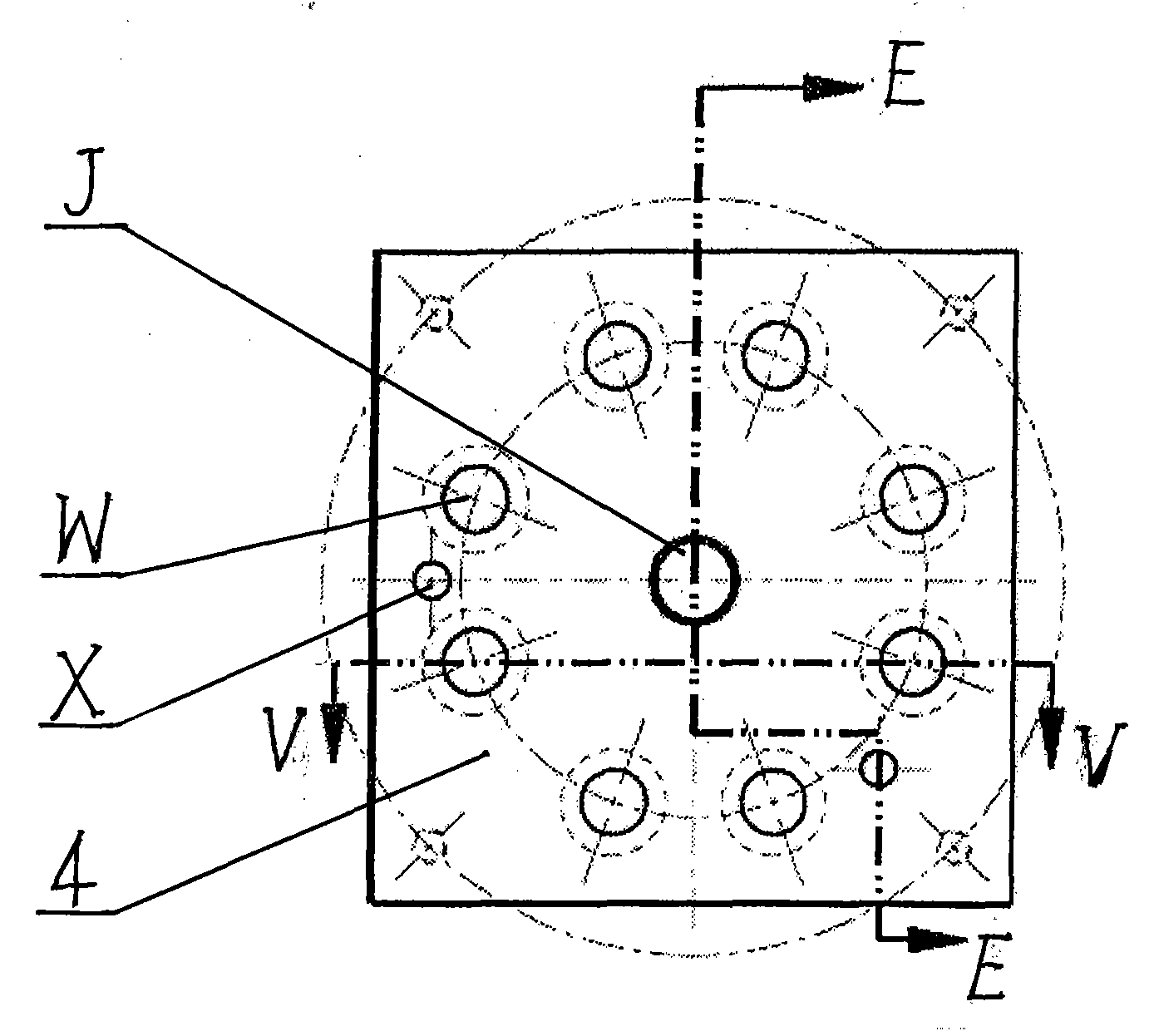
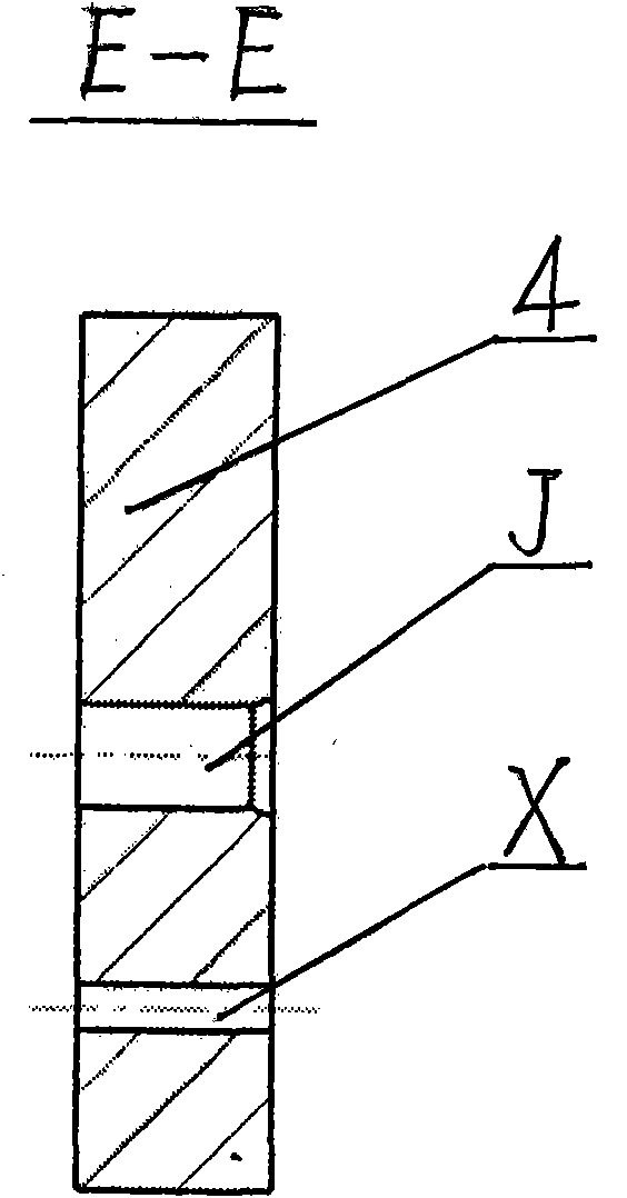
[0035] refer to figure 2 , image 3 , Figure 4 ...


PUM


Abstract

The invention relates to a swing type hydraulic proportioning and servo valve, wherein a valve core (6) is sheathed in a valve hole (R) at the center of the valve body (5). The two ends of the valve core (6) are enclosed by a valve cover (4) and a valve seat (7), so that a three-position four-way valve is assembled. The valve is matched with a swing motor (3) and an angular displacement sensor (1) and is controlled by a control chip. The valve body (5) is provided with an oil supply hole (P) and an oil return hole (T) at the front surface thereof, and an oil lifting hole (A) and an oil dropping hole (B) at the rear surface thereof. The oil supply hole (P), the oil return hole, the oil lifting hole (A) and the oil dropping hole (B) are respectively communicated with an oil tank through oil pipelines (L). The inner part of the valve body is communicated with the valve hole (R) through an oil-passing pipe cavity (N). One end of the valve core (6) passes out of the center hole of the valve cover (4) and is connected with the swing motor (3). The other end of the bidirectional output shaft of the swing motor (3) is connected with an angular displacement sensor (1). The control chip regulates the input current of the motor and the rotation angles of the output shafts in time according to the feedback information of the sensor, adjusts the swing angle of the valve core (6) and changes the sectional areas of openings of the oil holes so that the hydraulic flow and the pressure keep the design values. The swing motor can realize stepless speed regulation and stop in any positions within the swing range, and the swing type hydraulic proportioning and servo valve has the advantages of high control precision, good dynamical property, convenient and flexible operation and wide application range.

Description

technical field [0001] The invention relates to hydraulic components, in particular to a control valve for an oil cylinder of a hydraulic system. Background technique [0002] A hydraulic valve is a component used to control the pressure, flow and direction of a hydraulic fluid in hydraulic transmission, and its performance directly determines the overall effectiveness of the hydraulic system. Among various hydraulic flow and pressure control valves, proportional valves and servo valves are in great demand in the fields of aviation, aerospace, ships, metallurgy, and chemical industry because of their fast dynamic response and high control precision. How to improve proportional valves and servo valves The complex structure is the focus and difficulty in the field of hydraulic transmission and control. Most of the existing proportional valves and servo valves adopt the structure of slide valve and pilot valve. The complex structure and the processing requirements of high-prec...

Claims


Application Information

Patent Timeline
IPC IPC(8): F15B13/02
Inventor 庄健于德弘陈振国于新堂
Owner 山东通亚机械有限公司
Learn More