Driving device and driving method for synchronous rectifying tube

A synchronous rectifier tube and synchronous rectification technology, which is applied to the output power conversion device, the conversion of AC power input to DC power output, climate sustainability, etc. Signal acquisition difficulties and other problems, to achieve the effect of reducing costs, simple and effective synchronous rectification

Active Publication Date: 2010-12-01
VERTIV CORP
View PDF3 Cites 24 Cited by
  • Summary
  • Abstract
  • Description
  • Claims
  • Application Information

AI Technical Summary

Problems solved by technology

However, in topologies such as flyback conversion or LLC resonant conversion working in discontinuous current mode (DCM), it is more difficult to obtain the driving signal of the synchronous rectifier.
If the synchronous rectifier tube directly uses the same or reverse drive signal as the main power tube, there will be problems such as current backfeeding, which will seriously affect the normal operation of the circuit

Method used


Image

  • Driving device and driving method for synchronous rectifying tube
  • Driving device and driving method for synchronous rectifying tube
  • Driving device and driving method for synchronous rectifying tube

Examples


Embodiment 1

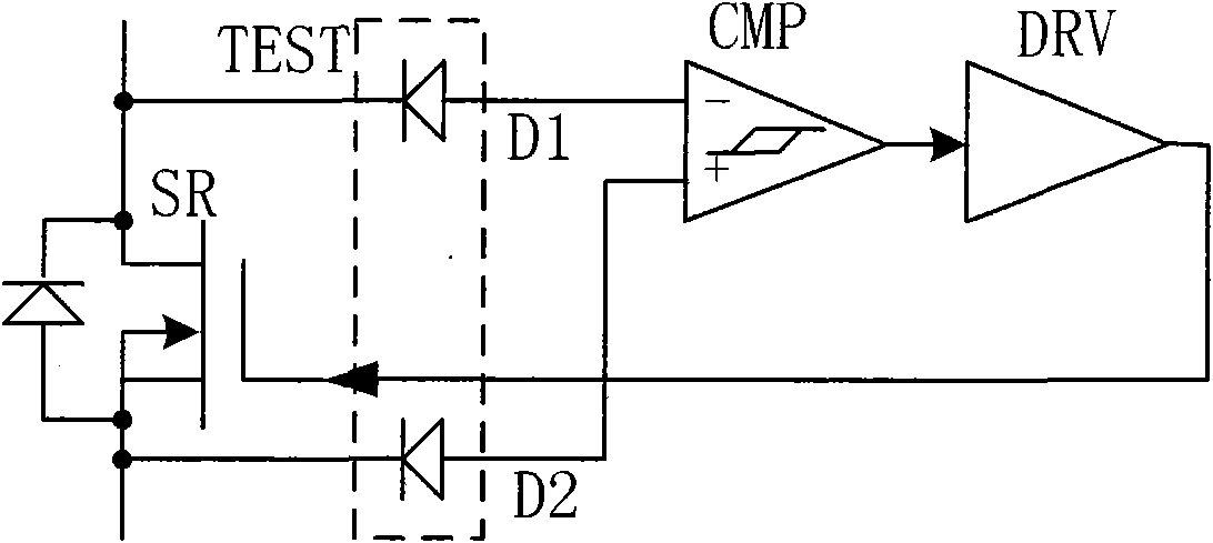
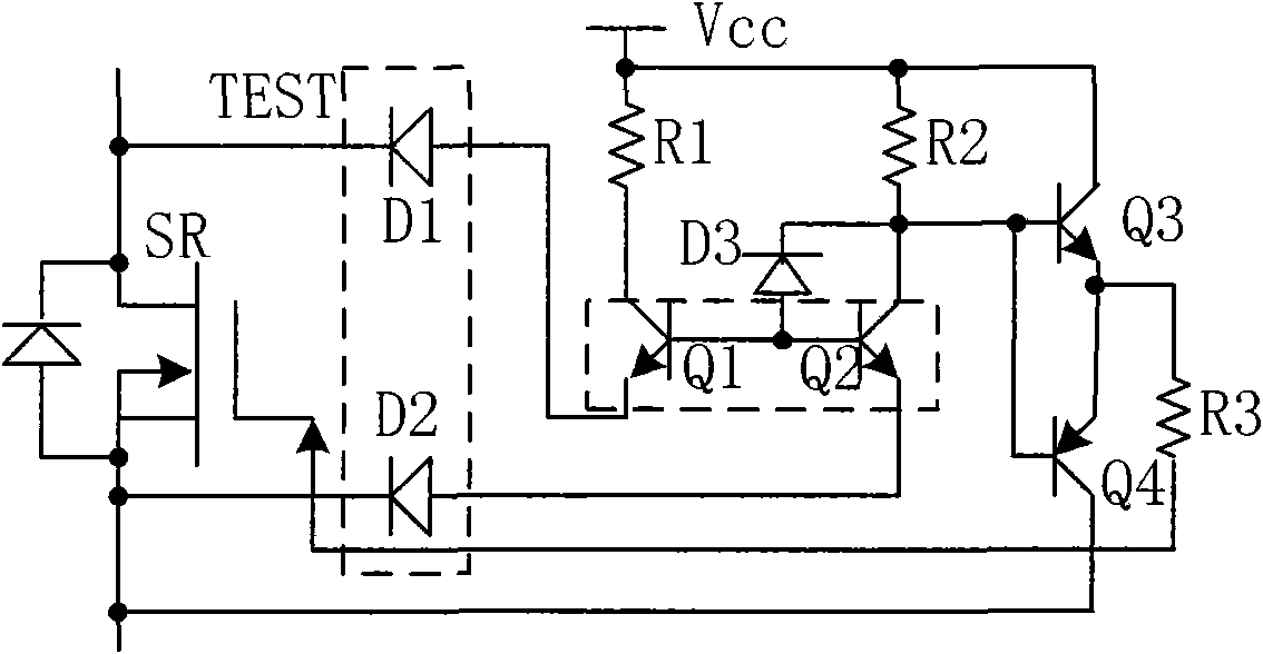
[0033] Such as image 3 As shown, the voltage detection isolation circuit TEST preferably includes a first diode D1 and a second diode D2, the cathode of the first diode D1 is connected to the drain of the synchronous rectification MOSFET SR, and the cathode of the second diode D2 is connected to The source of the synchronous rectification MOSFET SR, the anodes of the first diode D1 and the second diode D2 are respectively connected to the inverting input terminal - and the non-inverting input terminal + of the comparator CMP.

[0034] The comparison circuit CMP preferably includes a third diode D3, a first triode Q1 and a second triode Q2, wherein the emitter of the first triode Q1 is connected to the anode of the first diode D1, and the first triode The collector of the transistor Q1 is connected to the auxiliary power supply Vcc through the first resistor R1, the bases of the first transistor Q1 and the second transistor Q2 are connected to the anode of the third diode D3, ...

Embodiment 2

[0038] Such as Figure 4 As shown, the only difference from the previous embodiment is that the drive circuit uses an integrated drive IC chip instead of image 3 In the push-pull circuit composed of the third and fourth triodes Q3 and Q4. The input terminal of the integrated driver IC is coupled to the output terminal of the comparison circuit CMP, and its output terminal is coupled to the gate of the synchronous rectification MOSFET.


PUM


Abstract

The invention discloses a driving device for a synchronous rectifying tube, which is used for generating a driving signal for a synchronous rectifying MOSFET and comprises a voltage detection isolating circuit, a comparison circuit and a driving circuit, wherein the voltage detection isolating circuit is used for acquiring the drain voltage and source voltage of the synchronous rectifying MOSFET;the comparison circuit is used for comparing the drain voltage and with the source voltage of the synchronous rectifying MOSFET; and the driving circuit is used for generating a driving signal for the grid of the synchronous rectifying MOSFET based on the comparison result. The invention also discloses a driving method for the synchronous rectifying tube, comprising the following steps: detectingthe source voltage and the drain voltage of the synchronous rectifying MOSFET; comparing the drain voltage and with the source voltage of the synchronous rectifying MOSFET; and generating the drivingsignal for the grid of the synchronous rectifying MOSFET based on the comparison result. The invention can simply and effectively be obtained the driving signal for the synchronous rectifying tube ina changing circuit topology working in a discontinuous conduction mode.

Description

technical field [0001] The invention relates to synchronous rectification technology, in particular to a synchronous rectification tube driving device and a driving method. Background technique [0002] Obtaining higher efficiency is an important development trend of electric energy conversion devices. Synchronous rectification technology is a method commonly used to improve efficiency in low-voltage and high-current applications. Its basic principle is to replace the rectifier diode with a MOSFET (metal oxide semiconductor field effect transistor) with low on-resistance to reduce the conduction loss of the rectifier circuit. . In the Buck (step-down) hard switching conversion circuit and its derivative circuit topology, the control signal of the synchronous rectifier is the same as or reversed to that of the main power tube, so it is easier to obtain the drive signal of the synchronous rectifier. However, in topologies such as flyback conversion or LLC resonant conversion...

Claims


Application Information

Patent Timeline
Patent Type & Authority Applications(China)
IPC IPC(8): H02M7/217
CPCY02B70/1441Y02B70/10
Inventor 纪圣儒
Owner VERTIV CORP
Why Eureka
Try Eureka