Double-hearth high temperature smelting furnace

A high-temperature melting, dual-furnace technology, applied in furnaces, crucible furnaces, furnace types, etc., can solve the problems of furnace damage, sharp drop in crucible temperature, long transfer process time, etc. The effect of the furnace

Inactive Publication Date: 2010-12-08
UNIV OF SCI & TECH BEIJING
View PDF4 Cites 9 Cited by
  • Summary
  • Abstract
  • Description
  • Claims
  • Application Information

AI Technical Summary

Problems solved by technology

[0004] (2) The efficiency of batch testing is extremely low
Since this method is usually operated manually and the transfer process takes a long time, on the one hand, the crucible will be exposed to the air for a long time, which will easily cause the temperature of the crucible to drop sharply, which will cause the crucible to break or produce tiny cracks. The crucible breaks during the continuous heating process in the molybdenum rod furnace, and the internal material overflows into the furnace, causing damage to the furnace; high risk

Method used


Image

  • Double-hearth high temperature smelting furnace
  • Double-hearth high temperature smelting furnace

Examples


Embodiment Construction

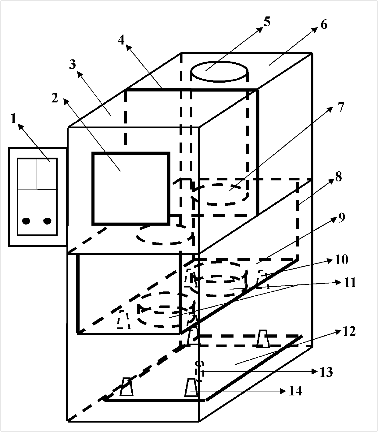
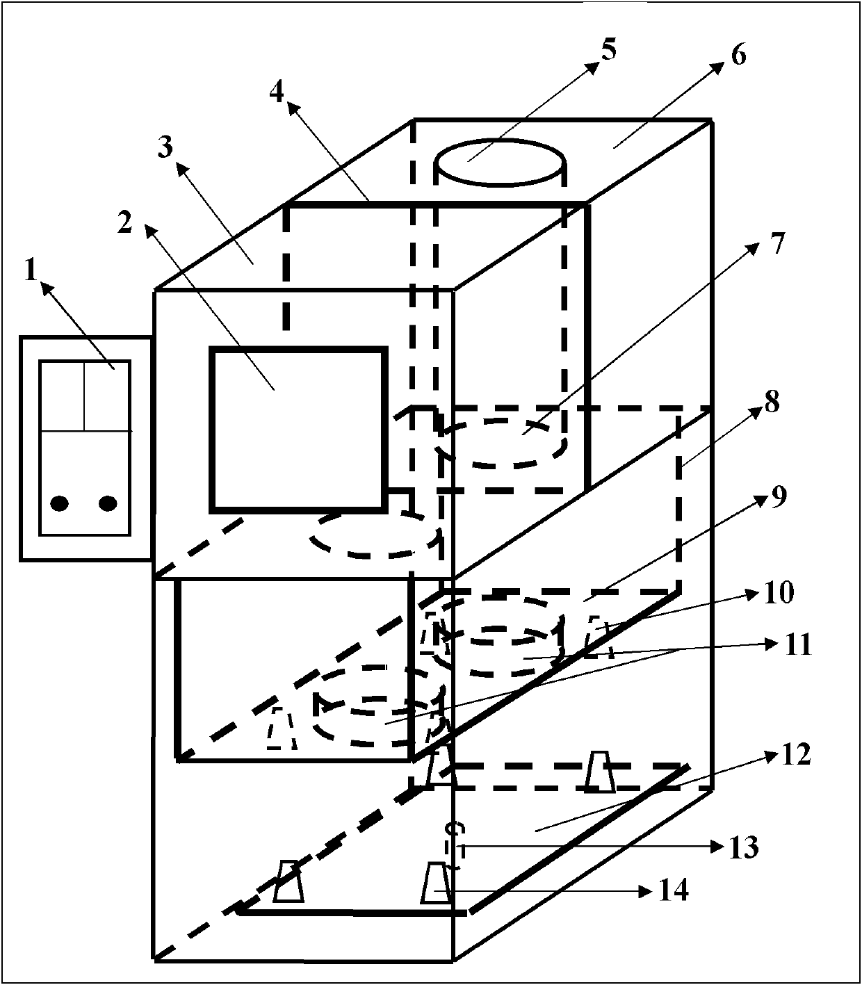
[0017] according to figure 1 And take melting converter slag as an example to further describe the embodiment of the present invention:

[0018] The main component of converter steel slag is SiO 2 , CaO , Al 2 o 3 , MgO, FeO, Fe 2 o 3 And elemental Fe, whose melting point is about 1600°C, was melted in a magnesia crucible for experiments.

[0019] First, put the weighed converter steel slag into the crucible, lower the furnace chassis 9, because it is the first time to heat up, the hollow ball refractory brick 11 and the furnace are at room temperature, so the crucible can be directly placed under the box furnace 3 Hollow ball refractory brick 11 at the front end of the control box 1, and then press the turn button on the control box 1 to drive the furnace bottom plate 9 to rotate backwards, so that the crucible is turned to the bottom of the pit furnace 6 at the rear end, so that the crucible can be avoided. Put it on the hollow spherical refractory brick below the rear...


PUM

PropertyMeasurementUnit
melting pointaaaaaaaaaa

Abstract

The invention discloses a double-hearth high temperature smelting furnace, and belongs to the technical field of electric heating. The double-hearth high temperature smelting furnace is characterized in that: a furnace body has a high temperature heating hearth and an ultrahigh temperature heating hearth at the same time, wherein the high temperature heating hearth has a box-type furnace structure with a lifting bottom, and the ultrahigh temperature heating hearth has a well-type furnace structure with a lifting bottom; and exchange of bottoms of the two heating hearths and heating materials can be realized through furnace bottom lifting and rotating mechanisms. The two heating hearths can be used separately or used at the same time. When the two hearths are used together, the material can be preheated in the high temperature hearth or further cooled, and the preheated material is further smelted in the ultrahigh temperature hearth or cooled. Through a double-hearth structure, the double-hearth high temperature smelting furnace realizes step heating of the material, ensures that a heating element runs in an optimal working area for a long term, improves the ultrahigh temperature smelting efficiency of batch materials by over two times, greatly shortens the material heating time and improves the operation safety.

Description

technical field [0001] The invention relates to a high-temperature melting furnace, which belongs to the technical field of electric heating. Background technique [0002] In the process of scientific research and production, the melting point of a large number of metal or non-metallic materials is higher than 1300°C. When heating such materials, the heating temperature often exceeds 1300°C. At present, the heating furnace used is generally an ultra-high temperature melting furnace in which the heating element is made of silicon molybdenum rods and the temperature can reach 1700 °C. However, this type of traditional silicon-molybdenum rod melting furnace has a single furnace structure, which has the following inherent disadvantages in the heating and cooling process: [0003] (1) The heating and cooling time is too long. For silicon-molybdenum rod furnace, it takes 2~3 hours to heat from room temperature to 1300°C, and about 2 hours from 1300°C to 1600°C; and it takes 2~3 ...

Claims


Application Information

Patent Timeline
Patent Type & Authority Applications(China)
IPC IPC(8): F27B14/06F27B14/08F27B14/20
Inventor 李宇宗燕兵杨志杰苍大强霍世明
Owner UNIV OF SCI & TECH BEIJING
Why Eureka
Try Eureka