

Closed flotation system with dross blowing device
A flotation and flotation cell technology, applied in flotation water/sewage treatment, etc., can solve the problems of slag scraper that is prone to failure, and achieve the effects of avoiding secondary pollution, overcoming scum overflow, and reliable work
- Summary
- Abstract
- Description
- Claims
- Application Information
AI Technical Summary
Problems solved by technology
Method used
Image

Examples
specific Embodiment approach 1
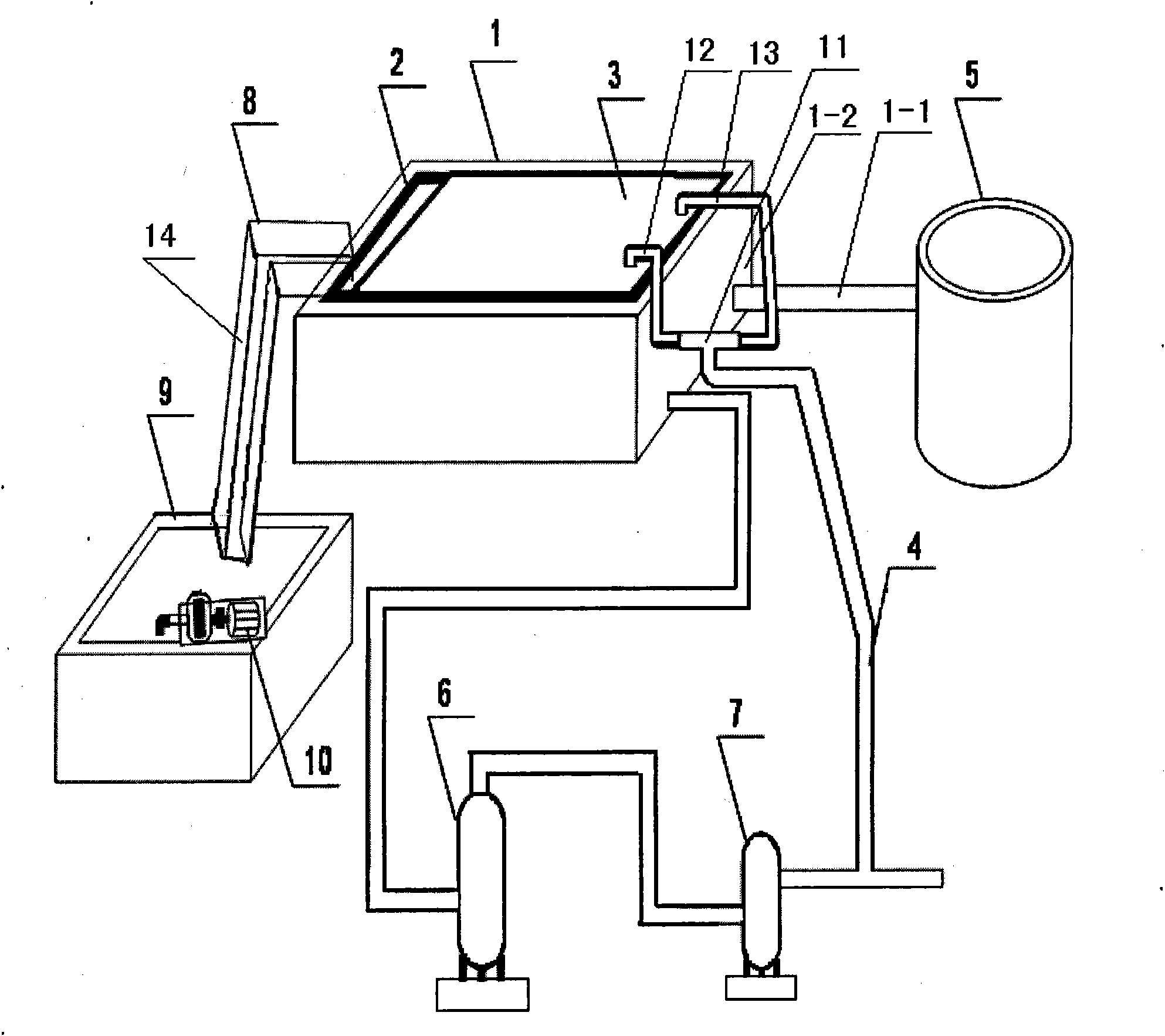
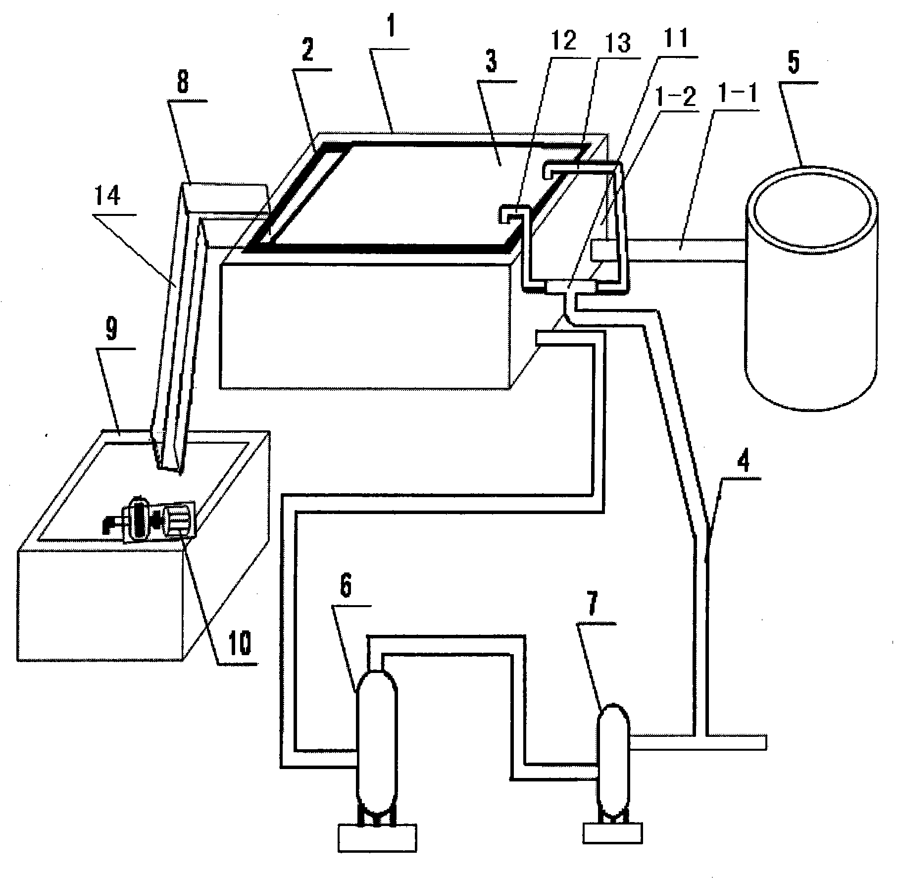
[0006] Specific implementation mode one: the following combination figure 1 This embodiment will be specifically described. figure 1 The part with the reference number 5 is the degreasing tank, and the waste water flowing out from the degreasing tank 5 flows into the flotation tank 1 through the waste water inlet pipe 1-1. This embodiment includes a flotation cell 1, which also includes a compressed air pipeline 4, a tee pipe joint 11, a No. 1 blowpipe 12, a No. 2 blowpipe 13, a sealing gasket 2, a sealing plate 3, a slag removal tank 8, and a scum tank 9 , chute 14 and water pump 10, sealing plate 3 is covered on the top of flotation cell 1 and the upper opening of flotation cell 1 is closed, and sealing pad 2 is arranged on the pool wall contact place of sealing plate 3 and flotation cell 1, compressed air One end of the pipeline 4 communicates with one end of the three-way pipe joint 11, and the other two ends of the three-way pipe joint 11 communicate with one end of the ...
specific Embodiment approach 2
[0007] Specific implementation mode two: the following combination figure 1 This embodiment will be specifically described. The difference between this embodiment and Embodiment 1 is that it also includes a container tank 6 and a buffer tank 7, the air inlet of the buffer tank 7 communicates with the compressed air pipeline 4, and the air outlet of the buffer tank 7 communicates with the air intake of the container tank 6 mouth, the gas outlet of container tank 6 communicates with the bottom of flotation cell 1. Such setting can make the slag deposited at the bottom of the flotation tank 1 be washed up by air bubbles, water flow, etc. generated by the gas fed in, so that the water can be treated more cleanly.
specific Embodiment approach 3
[0008] Specific implementation mode three: the following combination figure 1 This embodiment will be specifically described. The difference between this embodiment and Embodiment 1 is that the other end of the No. 1 blowpipe 12 and the other end of the No. 2 blowpipe 13 are evenly distributed along the length direction of the side wall 1 - 2 of the flotation cell 1 . Such setting makes the distribution of the air flow for purging the scum more reasonable.
PUM
 Abstract
Description
Claims
Application Information