
Mobile satellite communication multi-subarray panel antenna array and optimization method thereof

A technology for mobile satellite communication and flat-panel antennas, which is applied to antenna arrays, antennas, and independent antenna unit combinations, etc., and can solve problems such as sidelobe level rise, long transit time, and poor antenna pattern characteristics.

Inactive Publication Date: 2010-12-15
PLA SECOND ARTILLERY ENGINEERING UNIVERSITY
View PDF4 Cites 15 Cited by
  • Summary
  • Abstract
  • Description
  • Claims
  • Application Information

AI Technical Summary

Problems solved by technology

Due to the discrete aperture of the multi-sub-array flat panel antenna array itself, the performance of the antenna is greatly affected, and the side lobe level is high. At the same time, the instantaneous signal bandwidth of the antenna is small due to the long transit time of the aperture after splitting the plate.
To sum up, the flat panel antenna has obvious advantages in height, and can meet the requirements of various mobile carriers for its miniaturization and easy installation. Compared with a single panel antenna, the multi-subarray panel antenna array mainly brings two Problem: One is that the characteristics of the antenna pattern deteriorate and the level of the side lobe rises, and the other is that the instantaneous signal bandwidth of the antenna becomes smaller

Method used


Image

  • Mobile satellite communication multi-subarray panel antenna array and optimization method thereof
  • Mobile satellite communication multi-subarray panel antenna array and optimization method thereof
  • Mobile satellite communication multi-subarray panel antenna array and optimization method thereof

Examples


Embodiment Construction

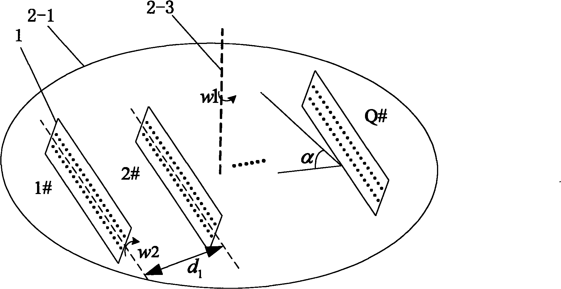
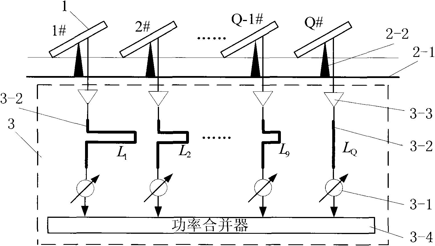
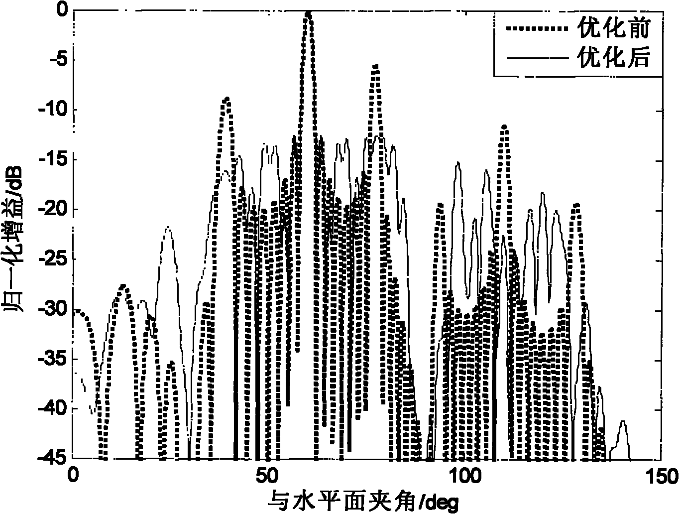
[0054] Such as figure 1 , figure 2 Shown a kind of mobile satellite communication multi-sub-array panel antenna array, comprises a plurality of panel antenna sub-arrays 1, the antenna turntable that is installed for a plurality of described panel antenna sub-arrays 1 and the radiation that is respectively connected in each panel antenna sub-array 1 Multiple feeder systems 3 between the unit and the signal transceiving port, multiple flat antenna sub-arrays 1 are installed in parallel on the antenna turntable, and the target elevation angles of the multiple flat antenna sub-arrays 1 aimed at the target satellite are all the same. The feeder system 3 includes a phase shifter 3-1 connected to the signal transceiving port and multiple sets of delay lines 3-2 connected between the radiation unit of the panel antenna sub-array 1 and the phase shifter 3-1, The number of the panel antenna sub-arrays 1 is Q and the distance between two adjacent panel antenna sub-arrays 1 is d i , wh...


PUM


Abstract

The invention discloses a mobile satellite communication multi-subarray panel antenna array and an optimization method thereof. The antenna array comprises a plurality of panel antenna subarrays, an antenna turntable and a plurality of feeder line systems connected between radiation units of the panel antenna subarrays and signal transceiving ports respectively, wherein the plurality of panel antenna subarrays are arranged in parallel on the antenna turntable and have the same target elevations; and the feeder line systems comprise phase shifters and a plurality of sets of delay lines. The optimization method comprises the following steps of: 1, setting parameters; 2, performing antenna subarray distance optimization by adopting an operation processor and using an improved genetic algorithm; and 3, performing delay line length optimization by adopting the operation processor. The antenna array has the advantages of simple structure, light weight, low height, low cost and convenient installation and layout; and the adopted optimization method has reasonable design and convenient implementation, and can effectively solve two practical problems between antenna radiation pattern characteristic variation of the multi-subarray panel antenna array and minor level rise and instantaneous signal bandwidth reduction of the antenna.

Description

technical field [0001] The invention relates to a multi-subarray antenna array for mobile satellite communication, in particular to a multi-subarray flat panel antenna array for mobile satellite communication and an optimization method thereof. Background technique [0002] Satellite communication system in motion refers to a system in which mobile carriers (such as automobiles, trains, airplanes, ships, etc.) realize real-time communication with target satellites (stationary or fixed-point satellites, that is, geostationary orbit satellites) during rapid operation. In actual work, because the distance between the target satellite and the ground is very long (about 40,000 kilometers), high-gain antennas must be used to achieve high-code-rate multimedia communication between the satellite and the ground carrier. Since the beam width of this antenna is very narrow, to ensure that the carrier can communicate with the satellite normally and uninterruptedly during the rapid movem...

Claims


Application Information

Patent Timeline
Patent Type & Authority Applications(China)
IPC IPC(8): H01Q1/12H01Q3/02H01Q21/00H01Q21/30
Inventor 姚敏立贾维敏林志强赵建勋秦丽平伍宗伟余伟平
Owner PLA SECOND ARTILLERY ENGINEERING UNIVERSITY
Learn More