Method for automatically checking topology in automatic test and automatic test system

An automated test and automatic inspection technology, applied in the field of data communication, can solve problems that affect the project test progress, consume manpower, and realize complex problems, so as to shorten the automated test cycle, facilitate maintenance, and achieve simple effects

Active Publication Date: 2010-12-15
MAIPU COMM TECH CO LTD
View PDF2 Cites 23 Cited by
  • Summary
  • Abstract
  • Description
  • Claims
  • Application Information

AI Technical Summary

Problems solved by technology

This will consume a lot of manpower to check the device connection, and a little careless operation may cause the already checked connection to be broken again
This will not only consume a lot of manpower, but also often delay the test plan due to equipment connection problems, seriously affecting the project test progress
In order to solve this problem, some automatic topology checking methods can be used to check the test equipment. Currently, the existing checking methods are roughly: one is to check the device connection through the link layer discovery protocol, and the implementation of this method is more complicated. , the other is to check through the link state change of the interface (that is, the correct entry of the link is: if the state of one end is up, then the other end is also up, and the other end is also down), this method The implementation is relatively simple, but due to the slow switching of the link status of general equipment, the link status needs to be switched repeatedly during the inspection process. In the case of a large number of inspected devices, the inspection efficiency is relatively low

Method used


Image

  • Method for automatically checking topology in automatic test and automatic test system
  • Method for automatically checking topology in automatic test and automatic test system
  • Method for automatically checking topology in automatic test and automatic test system

Examples


Embodiment Construction

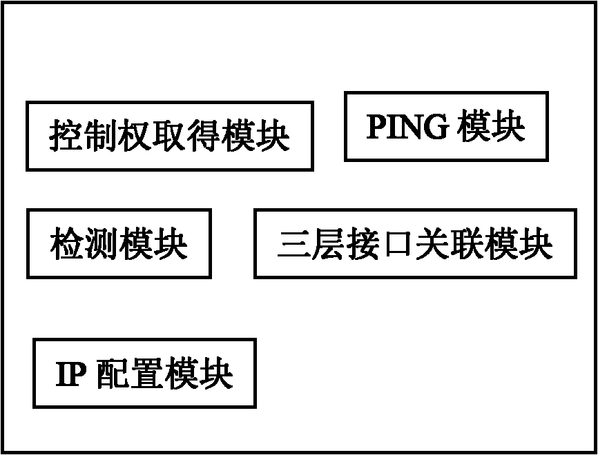
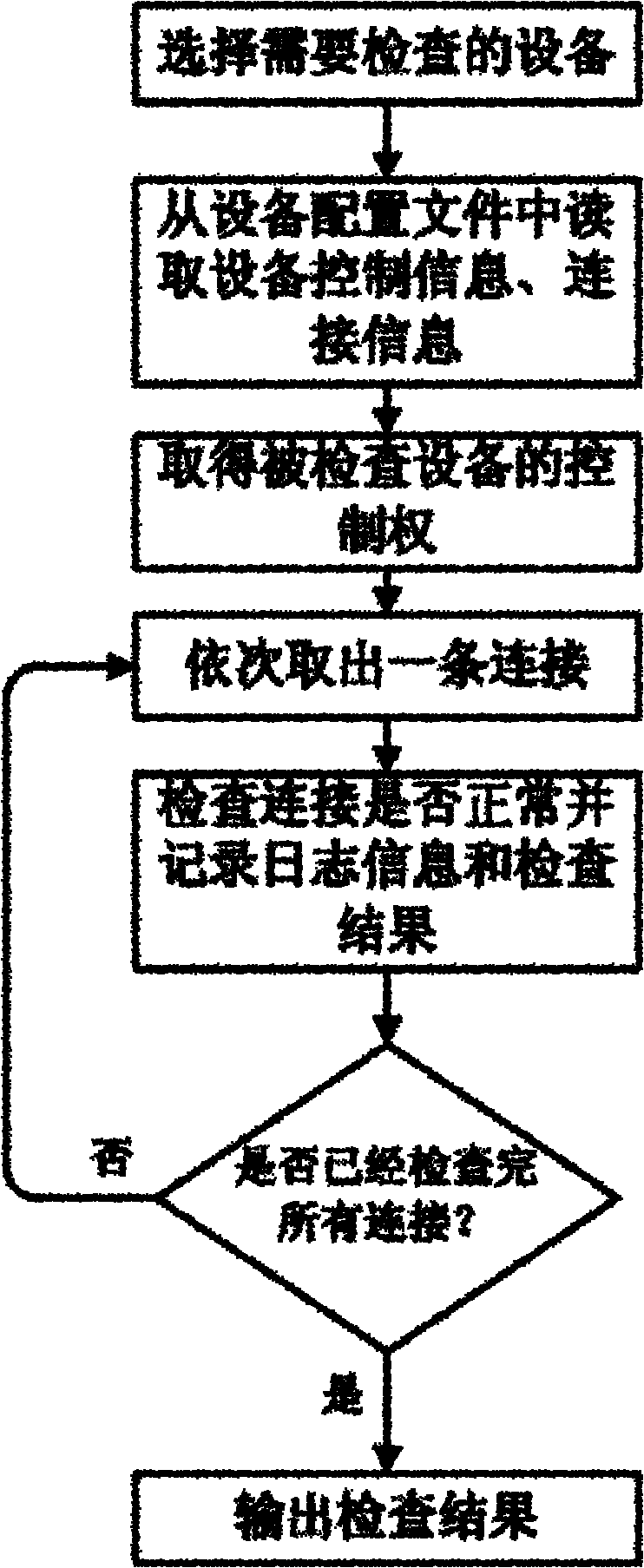
[0030] Such as figure 2 As shown, the control center includes a control right acquisition module, a PING module, a detection module, an IP configuration module, and a three-layer interface association module; image 3 Steps shown:

[0031] a. The control right acquisition module selects the device under test or auxiliary test device to be inspected;

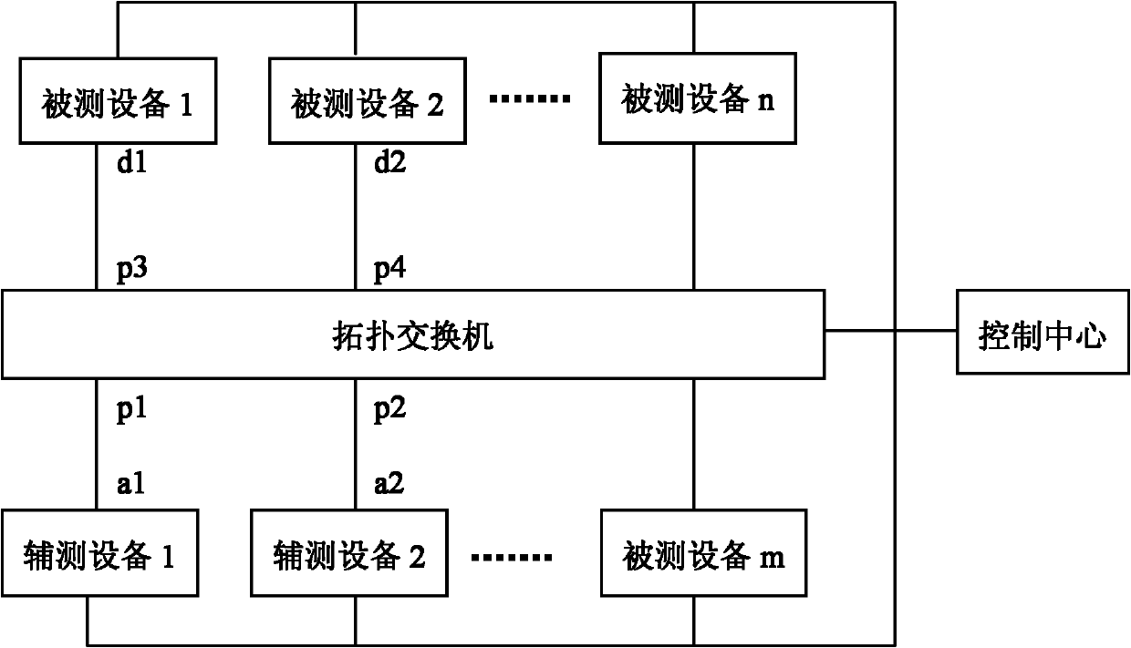
[0032] b. The control right acquisition module reads the control information and connection information of the selected device from the device configuration file; the device configuration file saves the device type and device name of all tested devices, auxiliary test devices, and topology switches in the automated test system , control IP, physical connection with the topology switch and other attributes;

[0033] c. The control right acquisition module obtains the control right of the selected device and the topology switch through the control information; the topology switch divides the port connected to the device under te...


PUM


Abstract

The technical problem to be solved of the invention is to provide a method and a system for automatically checking a topology in an automatic test, which have the advantages of simplicity and high detection efficiency. The method for automatically checking the topology in the automatic test comprises the following steps of: selecting a link of test equipment and a topology exchanger from link information in turn by using a control center; configuring an IP address of a three-layer interface, which is connected with the topology exchanger, on the test equipment; and controlling the test equipment to PING an IP address which is in the same network segment with the configured IP address but does not exist so as to trigger the test equipment to send an address resolution protocol (ARP) request message to the topology exchanger. The test equipment PINGs the IP address which does not exist to determine whether the link between the topology exchanger and the test equipment is normal or not. In the invention, the sending of the address resolution protocol (ARP) request message is triggered by using PING, the topology exchanger learns a media access control (MAC) address of the test equipment from the ARP request message and the control center determines whether the link is normal or not.

Description

technical field [0001] The invention relates to the automatic testing technology in the field of data communication. Background technique [0002] With the rapid development of automated testing technology in the field of data communication, more and more equipment manufacturers have used automated testing technology to shorten the equipment development cycle and development costs while ensuring product quality, and improve the market competitiveness of products. [0003] A typical automated test system includes a control center, a topology switch, multiple devices under test, and auxiliary test devices; each device under test and auxiliary test devices are connected to the topology switch, and the control center is connected to the topology switch, each device under test, Auxiliary testing equipment is connected. Among them, the equipment under test and the auxiliary test equipment are collectively referred to as test equipment. Such as figure 1 Shown: The system is divi...

Claims


Application Information

Patent Timeline
Patent Type & Authority Applications(China)
IPC IPC(8): H04L12/26
Inventor 郭静董哲
Owner MAIPU COMM TECH CO LTD
Why Eureka
Try Eureka