Waste heat utilizing device for internal combustion engine

An internal combustion engine and radiator technology, which is applied to steam engine devices, internal combustion piston engines, and mufflers, etc., can solve the problems of poor heat exchange performance of radiators, increased ventilation resistance, and reduced radiator ventilation, and achieve improved energy recovery. Efficiency, the effect of reducing ventilation resistance

Inactive Publication Date: 2010-12-15
SANDEN CORP
View PDF6 Cites 18 Cited by
  • Summary
  • Abstract
  • Description
  • Claims
  • Application Information

AI Technical Summary

Problems solved by technology

[0006] However, since such condensers are generally stacked on the front side of the radiator that cools the engine by the driving wind from the front of the vehicle, the ventilation resistance in front of the radiator increases so that the amount of ventilation toward the radiator is reduced, and there is a risk of heat dissipation. The problem of poor heat exchange performance of the device
[0007] In the prior art mentioned above, although the ventilation resistance in front of the radiator can be reduced by using the two condensers, the RC condenser and the AC condenser, as a common condenser, it is not possible to use the common condenser in the AC circuit and the RC circuit at the same time. The condenser cannot operate the waste heat utilization device when the air conditioner is running, so there are still technical problems in improving the energy recovery efficiency of the waste heat utilization device

Method used


Image

  • Waste heat utilizing device for internal combustion engine
  • Waste heat utilizing device for internal combustion engine
  • Waste heat utilizing device for internal combustion engine

Examples


Embodiment Construction

[0036] Hereinafter, one embodiment of the present invention will be described first, starting with the first embodiment, using the drawings.

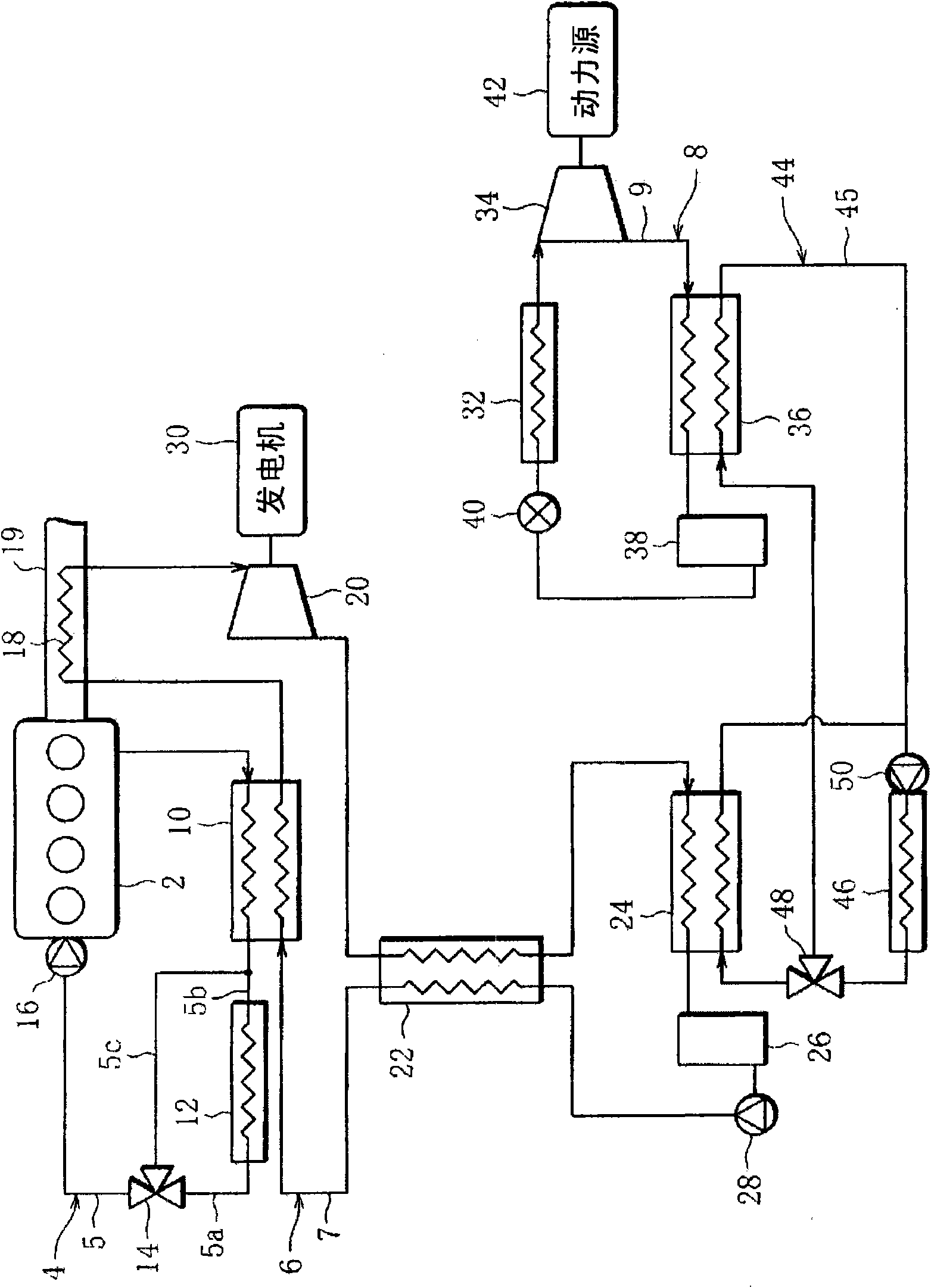
[0037] figure 1 It is a schematic diagram schematically showing the configuration of the waste heat utilization device of the internal combustion engine according to the present embodiment. The waste heat utilization device is installed in the vehicle, including: cooling water circuit 4, which cools the engine 2 of the vehicle; Rankine cycle circuit (Rankine cycle) 6 (hereinafter referred to as RC circuit), and the RC circuit 6 waste heat of the engine 2 is recovered; and an air-conditioning cycle (refrigeration cycle) 8 (hereinafter referred to as an AC circuit) for air-conditioning a vehicle interior (not shown).

[0038] In the cooling water circuit 4 , an evaporator 10 , a radiator 12 , a thermostat 14 , and a water pump 16 are connected sequentially from the cooling water flow direction to the cooling water circulation path 5 exte...


PUM


Abstract

Disclosed is a waste heat utilizing device for an internal combustion engine (2), which comprises a cooling water circuit (4) having a radiator (12) for cooling the cooling water with the draft of ambient air, a Rankine cycle (6) having a first condenser (24) for condensing a cooling medium, and a refrigerating cycle (8) having a second condenser (36) for condensing the cooling medium.The first and second condensers (24 and 36) are water-cooled heat exchangers, and include a water circuit (44) having an air-cooled heat exchanger (46) for cooling the water having passed the first and second condensers (24 and 36), with the draft of the ambient air, and a heat-exchanging unit (53) composed of the air-cooled heat exchanger (46) and the radiator (12).

Description

technical field [0001] The present invention relates to a waste heat utilization device of an internal combustion engine. Specifically, it relates to an ideal waste heat utilization device of an internal combustion engine installed in a vehicle. Background technique [0002] Such a waste heat utilization device of an internal combustion engine is installed in a vehicle, for example, and includes a Rankine cycle (RC circuit) that recovers waste heat with cooling water that cools the engine of the vehicle; and an air conditioning cycle (AC circuit). , the air conditioning cycle performs air conditioning in the vehicle interior. [0003] The RC circuit has: an expander that generates driving force by expanding evaporated refrigerant heated by recovered waste heat; and a Rankine cycle condenser (RC condenser) that makes the flow The refrigerant passing through the expander condenses. [0004] On the other hand, the AC circuit has: a compressor that compresses evaporated refrig...

Claims


Application Information

Patent Timeline
Patent Type & Authority Applications(China)
IPC IPC(8): F02G5/04F01P3/18F01P3/20
CPCF01K15/02Y02T10/166F01N5/02F01K23/065F01K9/003F02G2260/00F02G5/04Y02T10/16Y02T10/12
Inventor 粕谷润一郎荻原智德田正章齐藤智彦
Owner SANDEN CORP
Why Eureka
Try Eureka