Electric power supply device

A technology for power supply devices and vehicles, which is applied in the directions of electric power devices, vehicle energy storage, power devices, etc., to achieve the effects of compact structure, effective cooling, and compact configuration

Inactive Publication Date: 2010-12-22
HONDA MOTOR CO LTD
View PDF8 Cites 11 Cited by
  • Summary
  • Abstract
  • Description
  • Claims
  • Application Information

AI Technical Summary

Problems solved by technology

[0004] However, the above-mentioned existing invention cools the battery module and electrical components in parallel by providing the air intake duct on the front side of the vehicle body and the exhaust duct on the rear side of the vehicle body, and therefore is different from making the air intake duct and the exhaust duct on the vehicle body. Correspondingly, the front and rear separate settings have the problem of increasing the size of the power unit in the front and rear directions

Method used


Image

  • Electric power supply device
  • Electric power supply device
  • Electric power supply device

Examples


no. 1 approach

[0036] First, based on Figure 1 to Figure 8 A first embodiment of the present invention will be described.

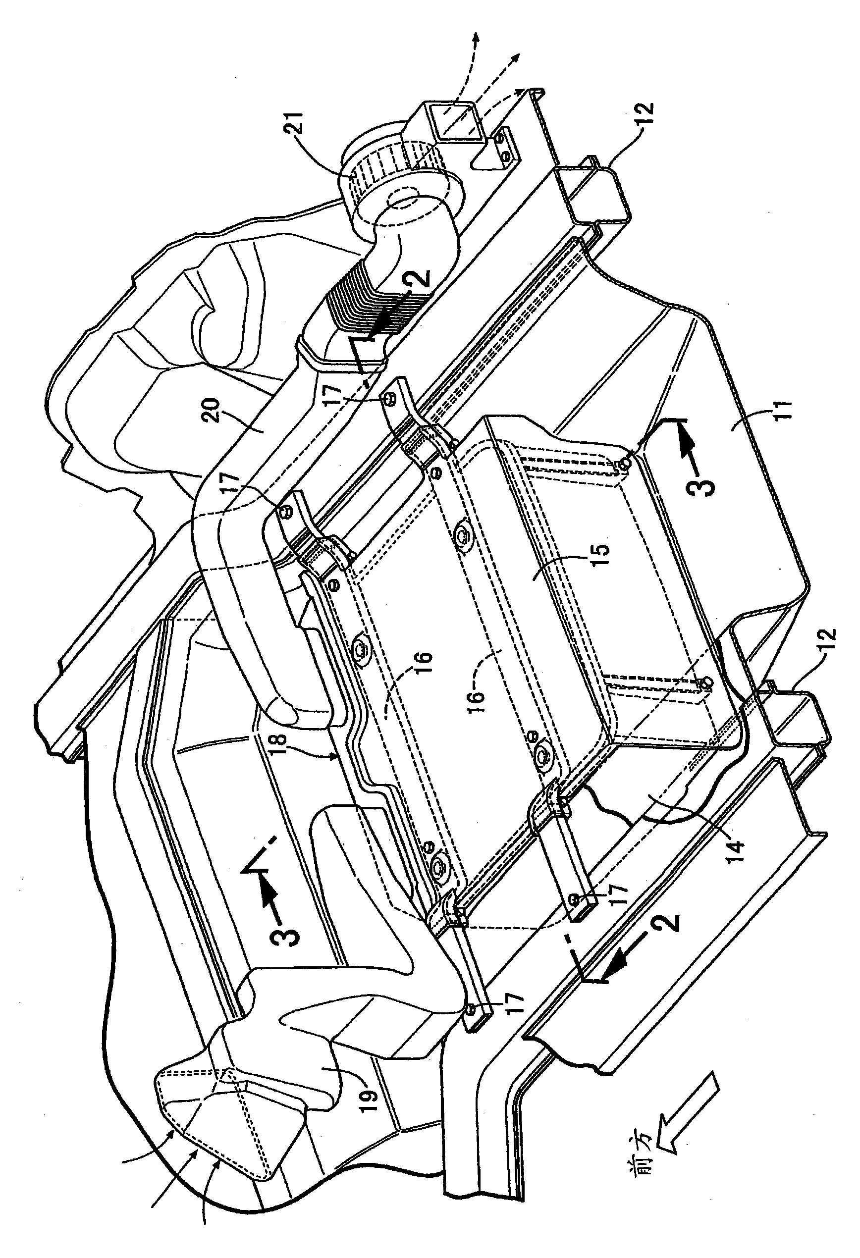
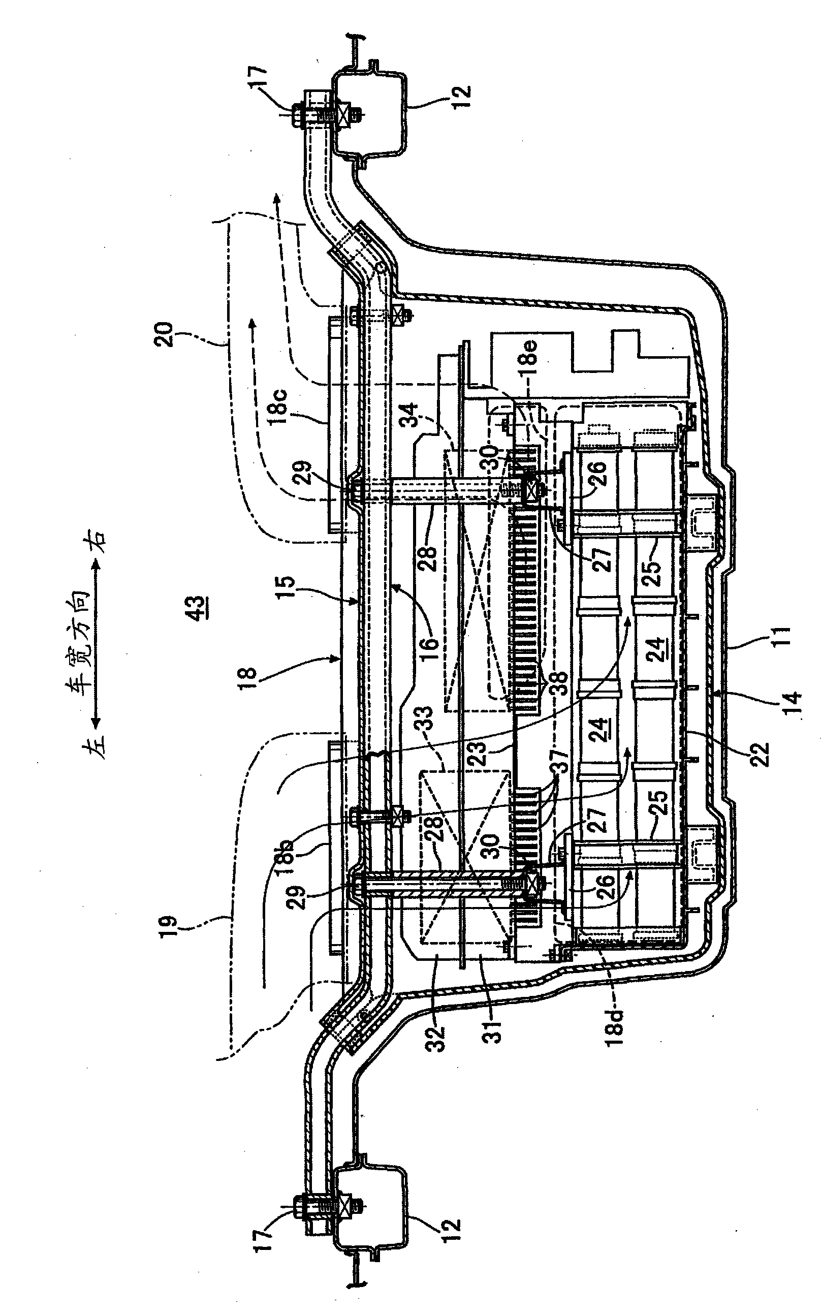
[0037] Such as figure 1 As shown, a power supply device for operating a motor / generator of a hybrid vehicle is accommodated by using a tire pan 11 in a trunk 43 at the rear of the vehicle body (refer to figure 2 and image 3 ) to accommodate the spare wheel. Left and right side edges of a container-shaped tire disc 11 depressed downward are connected to left and right rear side members 12 , 12 . The power supply unit includes a container-shaped waterproof case 14 with an open upper surface, a flat plate-shaped cover member 15 that closes the upper surface opening of the waterproof case 14, and a pair of front and rear suspension frames 16, 16 at both ends in the vehicle width direction. The pair of suspension frames 16 and 16 are fixed to the upper surfaces of the left and right rear side members 12 and 12 by bolts 17 . Therefore, the power supply unit is suspend...

no. 2 approach

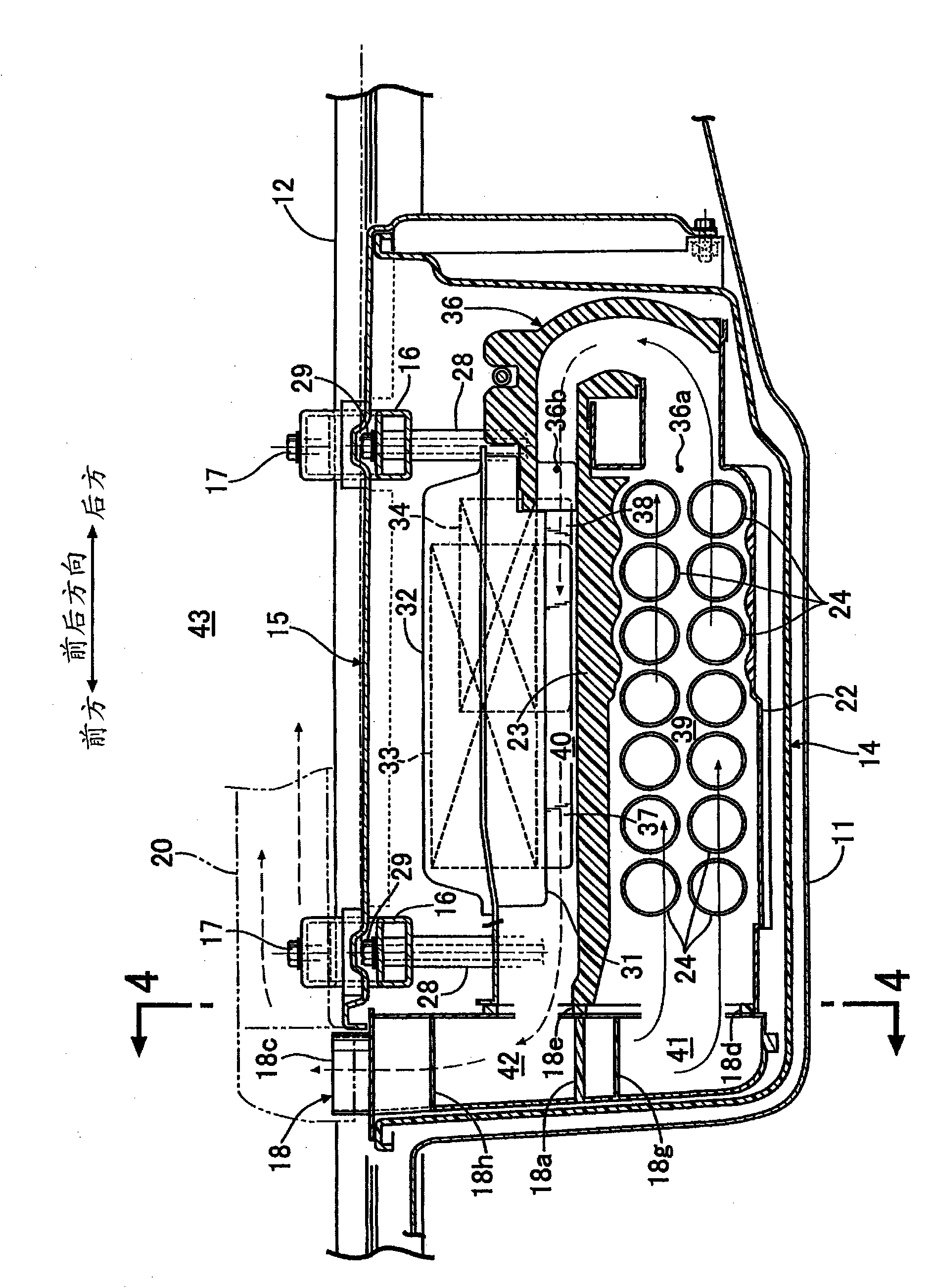
[0061] Next, based on Figure 9 A second embodiment of the present invention will be described.

[0062] The duct member 18 of the second embodiment is configured by combining the intake passage portion 41 and the exhaust passage portion 42 as separate members and integrally combining them. In this embodiment, although the number of components is increased compared with the first embodiment, the degree of freedom in designing the shape of the duct member 18 is increased.


PUM


Abstract

An electric power supply device in which the inside of a waterproof case (14) is partitioned into a lower first cooling air flow path (39) and an upper second cooling air flow path (40), cooling air introduced from an intake air flow path (41) of a duct (18) and flowing through the lower first cooling air flow path (39) cools a battery module (24), and after that, the cooling air is introduced into the upper second cooling air flow path (40) by an intermediate duct (36) to cool high-voltage electrical components (33, 34). Air heated by the high-temperature electrical components (33, 34) aftera cooling fan is stopped is discharged from a discharge air flow path (42) of the duct (18) without contact with the battery module (24) located below the components. Further, because the intake air flow path (41) and the discharge air flow path (42) are provided integrally in the duct (18) which is provided on one end side of the waterproof case (14), the electric power supply device is more compact than in the case where the intake air flow path (41) and the discharge air flow path (42) are separately provided at opposite ends of the waterproof case (14).

Description

technical field [0001] The present invention relates to a power supply device for a vehicle in which a power unit composed of an accumulator and electric components is arranged inside a case, and the inside of the case is divided into a first cooling air passage and a second cooling air passage , using the cooling air supply device to supply cooling air to the first and second cooling air passages, cooling the accumulator with the cooling air flowing through the first cooling air passage, and cooling the accumulator with the cooling air flowing through the second cooling air passage The cooling air cools the electrical components. Background technique [0002] In the following Patent Document 1, an invention is known in which a battery module is arranged in the lower part of a power supply unit arranged under the floor behind the seat of a motor vehicle, and a DC / DC converter is arranged in parallel in the vehicle width direction in the upper part. With the inverter for dri...

Claims


Application Information

Patent Timeline
Patent Type & Authority Applications(China)
IPC IPC(8): B60K11/06B60K1/04H01M10/50B60L50/64H01M10/60H01M10/613H01M10/625H01M10/643H01M10/652H01M10/6556H01M10/6563
CPCY02E60/12B60K1/04H01M2/1072H01M10/5097B60K2001/005H01M10/5016H01M10/5071B60K2001/0416H01M10/503H01M10/5073H05K7/20909H01M10/625H01M10/667H01M10/643H01M10/6565H01M10/6566Y02E60/10H01M50/249B60L50/64Y02T10/70
Inventor 久保田真也川田政夫
Owner HONDA MOTOR CO LTD
Why Eureka
Try Eureka