Composite oil cylinder

A technology of compound oil cylinder and auxiliary cylinder, applied in the direction of fluid pressure actuating device, etc., can solve the problems of long single cylinder length, complicated manufacturing process, large volume of hydraulic press, etc. Effect

Active Publication Date: 2010-12-29
HUZHOU MACHINE TOOL WORKS
View PDF3 Cites 17 Cited by
  • Summary
  • Abstract
  • Description
  • Claims
  • Application Information

AI Technical Summary

Problems solved by technology

[0002] The fast forward, fast reverse, working speed, buffering and other actions of the slider on most hydraulic machines are realized by external hydraulic control to drive the oil cylinder, but the traditional oil cylinder structure is difficult to achieve the above functions
The existing solution is to assist the work of the main oil cylinder through the external oil cylinder or the internal oil cylinder. The external oil cylinder has the disadvantages of large volume and complex structure of the hydraulic machine, and the internal oil cylinder mainly has the disadvantages of large single cylinder length and complicated manufacturing process.
For example, the State Intellectual Property Office of China published the patent No. "200320110440.X" on 2004-12-29, and the patent named "Composite Hydraulic Cylinder" adopts the composite structure of the rear cylinder and the front cylinder, and the rear cylinder acts on the front cylinder The tail is used to assist the piston rod of the front cylinder to achieve fast forward and fast reverse, but the oil cylinder of this composite structure still has the disadvantage of large single cylinder length. Another example is the "multifunctional combination In the "Oil Cylinder" patent, the structure of adding a quick cavity and a buffer cavity in the inner cavity of the crude oil cylinder is used to realize fast forward, fast reverse, working forward, buffering, etc., but the disadvantage is that the length of the single cylinder is also increased

Method used


Image

  • Composite oil cylinder
  • Composite oil cylinder
  • Composite oil cylinder

Examples


Embodiment Construction

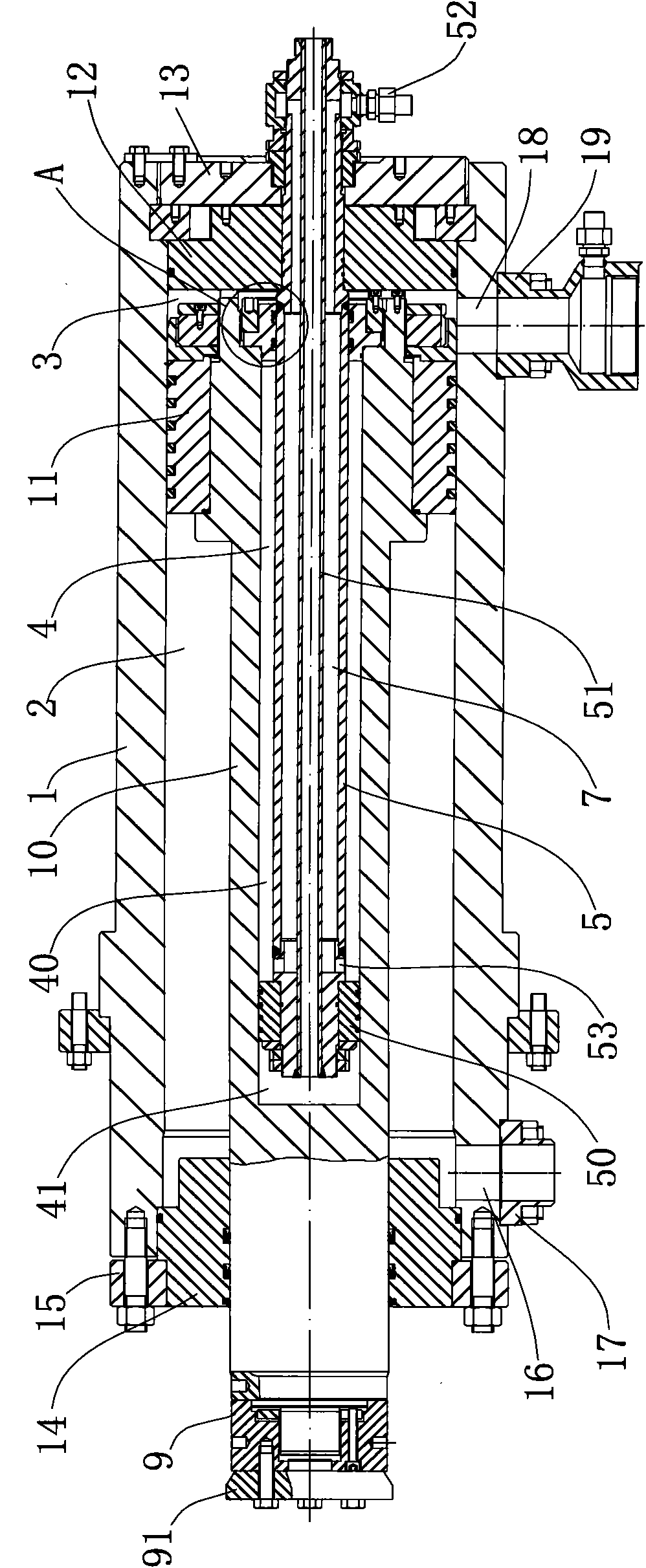
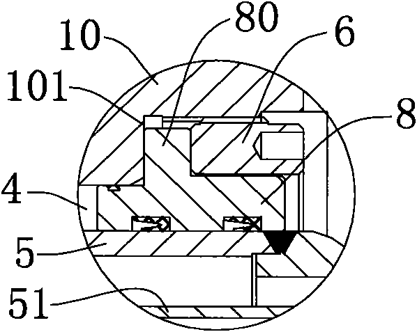
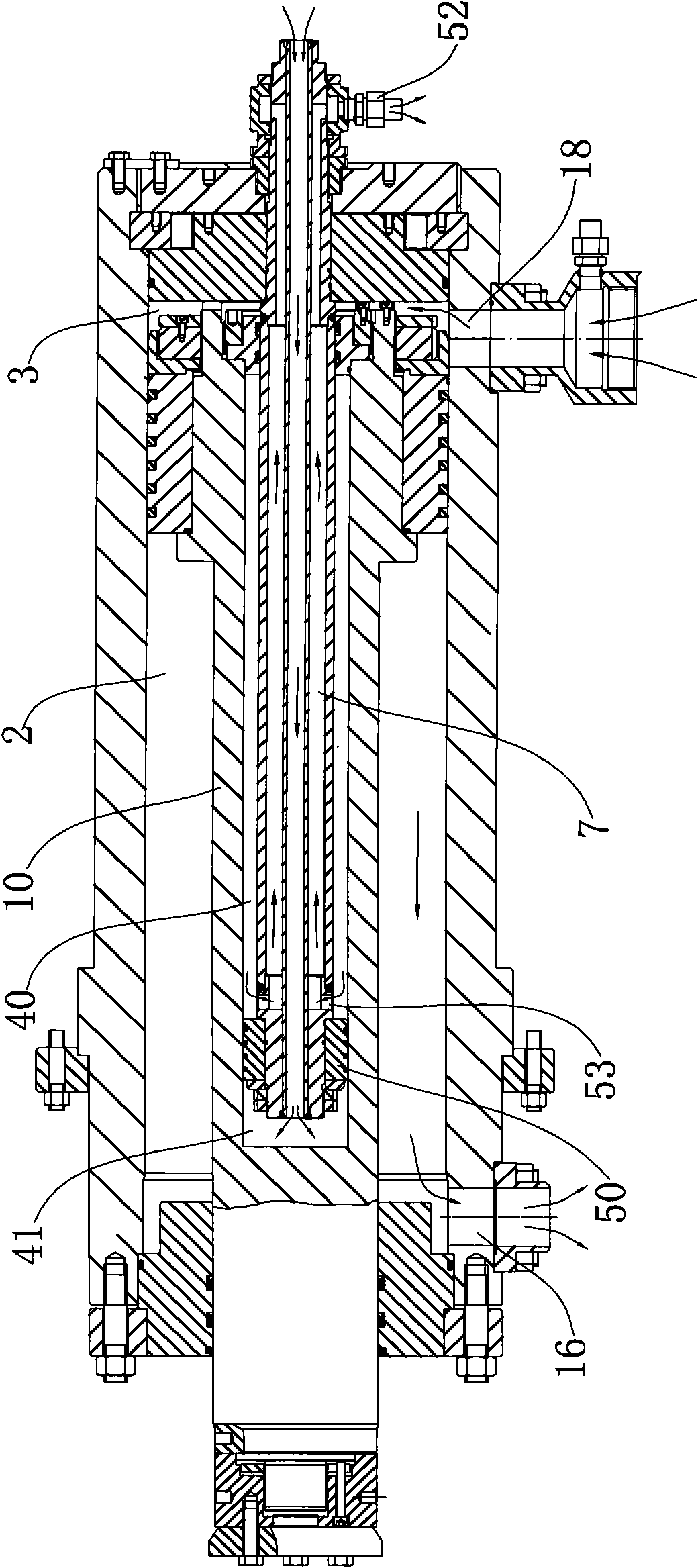
[0019] Such as figure 1 , figure 2 As shown, the present invention is a composite oil cylinder, comprising a master cylinder assembly and an auxiliary cylinder assembly, the master cylinder assembly comprising a master cylinder body 1, a master piston rod 10 and a master piston 11 disposed in the master cylinder body 1, and a The master cylinder rear cover assembly at the tail of the master cylinder 1, the master piston 11 divides the inner cavity of the master cylinder 1 into the master cylinder pressure chamber 3 and the master cylinder return chamber 2, and the master cylinder 1 is provided with a connecting master cylinder The pressure chamber 3 is connected to the oil inlet part of the fuel tank, and the main cylinder return chamber 2 is connected to the oil outlet part of the fuel tank. The main piston rod 10 is provided with a main rod inner chamber 4 with one end open, and the auxiliary cylinder assembly includes a wear The auxiliary piston rod 5 in the main rod inne...


PUM


Abstract

The invention discloses a composite oil cylinder, which comprises a main cylinder assembly and a secondary cylinder assembly, wherein the main cylinder assembly comprises a main cylinder body, a main piston rod and a main piston arranged in the main cylinder body, and a main cylinder rear cover assembly arranged at the tail part of the main cylinder body; the main piston divides the cavity of themain cylinder body into a main cylinder pressing cavity and a main cylinder return cavity; the main cylinder body is provided with an oil inlet part for communicating the main cylinder pressing cavity and an oil tank and an oil outlet part for communicating the main cylinder return cavity and the oil tank; a main rod cavity with one open end is formed in the main piston rod; the secondary cylinder assembly comprises a secondary piston rod passing through the main rod cavity, a secondary piston arranged at the inner end of the secondary piston rod and used for dividing the main rod cavity intoa secondary cylinder pressing cavity and a secondary cylinder turn cavity, an oil inlet structure for communicating the secondary cylinder pressing cavity and the oil tank, and an oil outlet structure for communicating the secondary cylinder return cavity and the oil tank; the outer end of the secondary piston rod is fixed on the main cylinder rear cover assembly; and an oil seal assembly linked with the main piston rod is arranged between the open end wall of the main rod cavity and the outer wall of the secondary piston rod and used for closing the secondary cylinder return cavity.

Description

technical field [0001] The invention belongs to a power executive component on hydraulic equipment, in particular to a compound oil cylinder. Background technique [0002] The fast forward, fast reverse, working speed, buffering and other actions of the slider on most hydraulic machines are realized by external hydraulic control to drive the oil cylinder, but the traditional oil cylinder structure is difficult to achieve the above functions. The existing solution is to assist the work of the main oil cylinder through the external oil cylinder or the internal oil cylinder. The external oil cylinder has the disadvantages of large volume and complex structure of the hydraulic machine, and the internal oil cylinder mainly has the disadvantages of large single cylinder length and complicated manufacturing process. . For example, the State Intellectual Property Office of China published the patent No. "200320110440.X" on 2004-12-29, and the patent named "Composite Hydraulic Cylin...

Claims


Application Information

Patent Timeline
Patent Type & Authority Applications(China)
IPC IPC(8): F15B15/16
Inventor 华强
Owner HUZHOU MACHINE TOOL WORKS
Why Eureka
Try Eureka