
Transistor test device and method

A testing device and transistor technology, applied in the field of microelectronics, can solve the problems of complicated and complicated testing of CMOS devices, and achieve the effect of monitoring structure

Active Publication Date: 2012-08-01
BEIJING ZHONGKE XINWEITE SCI & TECH DEV
View PDF0 Cites 1 Cited by
  • Summary
  • Abstract
  • Description
  • Claims
  • Application Information

AI Technical Summary

Problems solved by technology

[0006] The present invention is proposed in view of the cumbersome and complicated problem of CMOS device testing in the related art. Therefore, the main purpose of the present invention is to provide a transistor testing device and method to solve at least one of the above-mentioned problems

Method used


Image

  • Transistor test device and method
  • Transistor test device and method
  • Transistor test device and method

Examples


Embodiment Construction

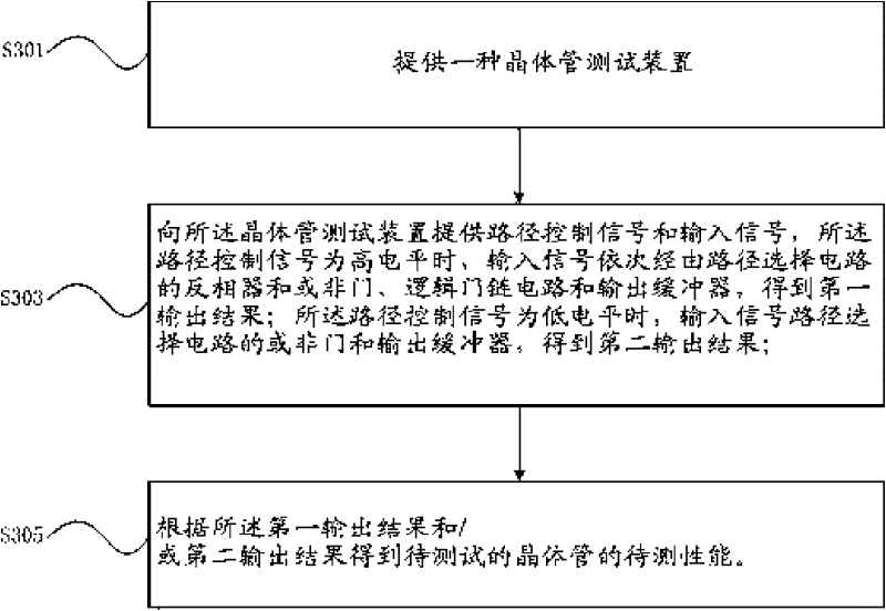
[0022] In the embodiment of the present invention, a transistor test scheme is provided. In this implementation scheme, a transistor test device with simple design and easy operation is used to test the transistor to be tested by using a test method corresponding to the test device to obtain a transistor The relevant performance of the transistor is used to determine whether the transistor meets the performance index requirements.

[0023] It should be noted that, in the case of no conflict, the embodiments in the present application and the features in the embodiments can be combined with each other. The present invention will be described in detail below with reference to the accompanying drawings and examples.

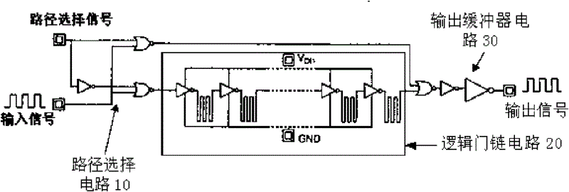
[0024] According to an embodiment of the present invention, a transistor testing device is provided. figure 1 It is a structural block diagram of a transistor testing device of the present invention. Such as figure 1 As shown, the transistor test setup includes: ...


PUM


Abstract

The invention provides a transistor test device and method, belonging to the technical field of microelectronics. The transistor test device comprises a routing circuit, a logic gate chain circuit and an output buffer circuit, wherein the routing circuit is used to receive routing signals and input signals and control the paths of the input signals according to the routing signals; the logic gatechain circuit is coupled with the routing circuit and ensures that signals pass through the logic gate chain circuit to form tested signals; the logic gate chain circuit is a cascade circuit composedof an even number of cascaded gate circuits, each gate circuit comprises a transistor to be tested; and the output buffer circuit is coupled with the logic gate chain circuit and the routing circuit respectively and used to receive the middle signals from the logic gate chain circuit or the routing circuit and output the buffered output result. By adopting the technical scheme of the invention, the transistor test device and method are provided, thus solving the test problem of the transistor in packaging mode, monitoring the technology and the structure of the element and testing the transistor conveniently and practically.

Description

technical field [0001] The invention relates to the technical field of microelectronics, in particular to a testing device for a Metal-Oxide-Semiconductor (MOS) transistor. Background technique [0002] At present, MOSFET and related circuits are widely used, among which the complementary MOS (CMOS) process has become the mainstream process in bulk silicon integrated circuit technology due to its advantages of high integration density, low static power consumption, and strong anti-interference ability. [0003] Integrated circuits have developed into the current ultra-large-scale era. To further increase the integration and operating speed of chips, the existing bulk silicon processes are approaching their physical limits. As the feature size of the device shrinks, the interaction between the PN junction inside the device and between the device and the device through the substrate is becoming more and more serious, and a series of new problems in materials, device physics, d...

Claims


Application Information

Patent Timeline
Patent Type & Authority Patents(China)
IPC IPC(8): G01R31/26
Inventor 毕津顺海潮和韩郑生罗家俊
Owner BEIJING ZHONGKE XINWEITE SCI & TECH DEV
Learn More