Low-pass filter

A technology of low-pass filter and metal disk, which is applied in the direction of waveguide devices, impedance networks, electrical components, etc., and can solve the problems of large reflection loss, large structure volume, and inability to ensure wide-band high attenuation in the stop band. , to achieve the effect of reducing insertion loss and broadening the band resistance characteristics

Inactive Publication Date: 2013-01-23
TYCO ELECTRONICS (SHANGHAI) CO LTD
View PDF3 Cites 0 Cited by
  • Summary
  • Abstract
  • Description
  • Claims
  • Application Information

AI Technical Summary

Problems solved by technology

[0010] but, Figure 5 The coaxial line filter shown has the following disadvantages: because the internal signal conductor of the high-impedance line is relatively thin, a metal sheet or metal plate is loaded on it, which increases the difficulty of processing and manufacturing
[0013] but, image 3 The main drawbacks of the periodic structure waveguide shown are: 1) A large number of metal periodic modules (at least ten, sometimes even dozens of metal periodic modules) must be present to provide effective passband and stopband frequency characteristics , the existence of a large number of metal periodic modules makes the structural volume of the periodically loaded waveguide transmission line larger; 2) Due to the limitation of the structural volume, the number of metal periodic modules cannot be infinitely large, resulting in multiple periodic bandpass frequency regions Close, can not filter out high-order harmonics, and can not ensure high attenuation of broadband in the stop band; 3) When the periodic structure waveguide is connected to the external ordinary transmission line, special impedance matching units or connectors are required, otherwise, due to their The characteristic impedance of the connection does not match, and there will be a large reflection loss at the connection, which cannot ensure low insertion loss within the bandwidth of the passband.

Method used


Image

  • Low-pass filter
  • Low-pass filter
  • Low-pass filter

Examples


no. 1 example

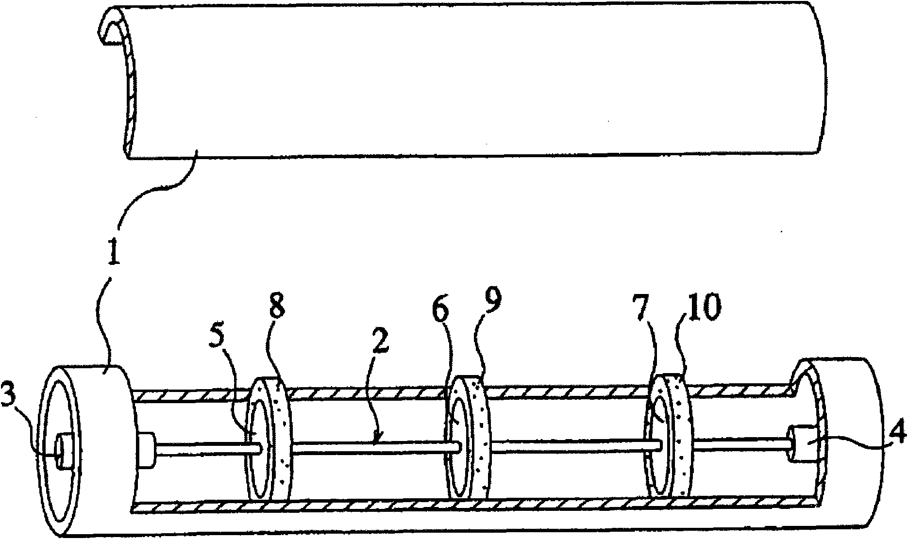
[0050] Image 6 , 7 and Figure 10 A first exemplary embodiment of the low-pass filter of the present invention is shown. specifically, Image 6 A schematic diagram showing a three-dimensional structure of an embodiment of the filter of the present invention; Figure 7 show Image 6 Axial sectional view of the filter shown; Figure 10 show Image 6 The frequency response characteristic curve of the filter of the present invention is shown.

[0051] like Image 6 As shown, in this embodiment, the filter includes: a cylindrical outer ground conductor 1; an inner signal conductor 2 concentrically arranged in the outer ground conductor 1; three inner signal conductors arranged at equal intervals on the inner signal conductor 2. A first metal disc 5, 6, 7; two second metal discs 11, 12 respectively arranged at both ends of the internal signal conductor 2; an input terminal 3 connected to one end of the internal signal conductor 2; and The other end of the internal signal c...

no. 2 example

[0070] Figure 11 A schematic structural diagram of an exemplary second embodiment of the low-pass filter of the present invention is shown.

[0071] like Figure 11 As shown, the difference between the low-pass filter shown in the second embodiment and the low-pass filter shown in the first embodiment is only that two first metal discs 5, 7 are provided, unlike the first embodiment Three first metal discs 5, 6, 7 are set as an example.

[0072] It should be noted that, in the present invention, the number of the first metal disks can be not only two, three, but also four or more.


PUM


Abstract

The invention discloses a low-pass filter which consists of a periodic-structure coaxial line and an impedance matching unit thereof. The low-pass filter comprises an external grounding conductor with a round hollow cavity, an internal signal conductor arranged in the round hollow cavity of the external grounding conductor, two or more first metal disks arranged at the middle part of the internalsignal conductor, and two same second metal disks respectively arranged at the two ends of the internal signal conductor. In the invention, the impedance matching of the periodic-structure coaxial line and an external common transmission line is completed through respectively setting one second metal disk with relatively smaller diameter at the two sides of the first metal disk with relatively larger diameter. Through utilizing the impedance matching unit, the invention effectively reduces the insertion loss of a periodic-structure transmission line, improves the frequency passing characteristic of a low-pass band, broadens the stop band frequency range of the periodic-structure transmission line, and sufficiently attenuates the high-frequency components above the cutoff frequency in a wide stop band range greater than the cutoff frequency.

Description

technical field [0001] The invention relates to a low-pass filter, in particular to a periodic structure coaxial line low-pass filter used in a microwave frequency band. Background technique [0002] figure 1 is a conventional coaxial line filter (low-pass filter) disclosed in Reference Document 1 ('Microwave Filters, Impedance-Matching Network, and Coupling Structures' G.L. Matthaei et.al, 1962, McGrawHill, p.365-374) Partial exploded perspective view of the structure. In the figure, reference numeral 1 denotes an outer ground conductor having a cylindrical shape with a circular hollow inner cavity, and reference numeral 2 denotes a cylinder which is isolated from the outer ground conductor 1 at an inner concentric position of the outer ground conductor 1 Shaped internal signal conductor, reference numeral 3 represents an input terminal connected to one end of the internal signal conductor 2, reference numeral 4 represents an output terminal connected to the other end of ...

Claims


Application Information

Patent Timeline
Patent Type & Authority Patents(China)
IPC IPC(8): H01P1/202H03H7/01H03H1/00
Inventor 严忠友
Owner TYCO ELECTRONICS (SHANGHAI) CO LTD
Why Eureka
Try Eureka