Device for injecting compressed air into a blow mold

A technology of compressed air and cylinders, which is applied in applications, household components, household appliances, etc., and can solve problems such as expensive, poor stop vibration, high production costs, etc.

A technology of compressed air and cylinders, which is applied in applications, household components, household appliances, etc., and can solve problems such as expensive, poor stop vibration, high production costs, etc.

CN101939155AInactive Publication Date: 2011-01-05오이겐자이츠아게

Image

  • Device for injecting compressed air into a blow mold
  • Device for injecting compressed air into a blow mold
  • Device for injecting compressed air into a blow mold

Examples


Embodiment Construction

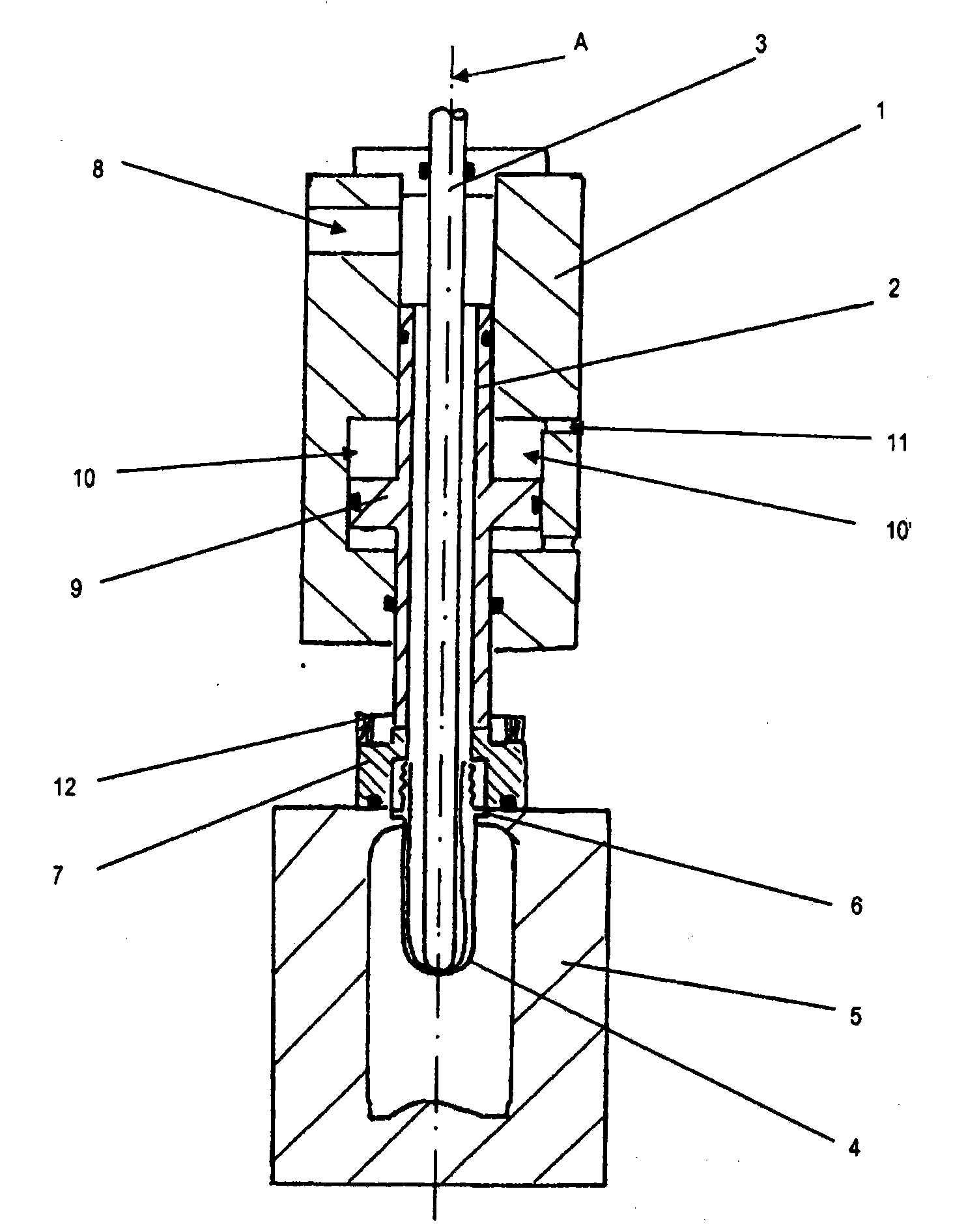
[0031] exist figure 1shows a fully schematic longitudinal section of a conventional blow molding cylinder of a stretch blow molding machine for producing eg PET bottles. A stretch rod 3 is arranged coaxially with respect to the hollow shaft 2 in the housing 1 of the blow molding cylinder. The stretch rod 3 protrudes upwards from the housing 1 leading to a separate drive for the stretch rod 3 (not shown). The lower end of the stretch rod 3 leads in a lowered state into the parison 4 of the PET bottle to be blown, which is itself secured in the blow mold 5 by its neck ring 6 .

[0032] At its lower end, the hollow shaft 2 has a sealing bell 7 which, in the example shown, is in tight contact with the upper side of the blow mold 5 in the operating position of the hollow shaft 2 . Now via the pressure tube 8 compressed air can be blown down through the hollow shaft 2 into the parison 4 and the parison is blown into its final shape according to the shape of the blow mold 5 . Ther...


PUM


Abstract

The invention relates to a device for injecting compressed air into a parison, having an injection cylinder, having a hollow shaft (2) arranged inside the housing (1) of the injection cylinder in a manner so as to be displaceable along its longitudinal axis (A), one end of said hollow shaft projecting out of the housing (1) and provided with a connection head (7) for a tight connection to the parison, and having a stretching rod (3) arranged coaxially to the hollow shaft (2) in the interior of the hollow shaft (2) and displaceable coaxially with the hollow shaft (2). A double piston (21, 22) is arranged axially parallel to the hollow shaft (2). The double piston (21, 22) is connected to the hollow shaft (2) by a connection lug (25) and thereby moves the hollow shaft along its longitudinal axis (A) between a lower and an upper end position. The drive of the hollow shaft (2) therefore takes place not coaxially, but rather from the side via a piston axis (B) arranged parallel to the longitudinal axis (A) of the hollow shaft (2). In this way, the functioning of the air supply via the hollow shaft (2) and the movement of the coaxially arranged stretching rod (3) is separated from the drive of the hollow shaft (2).

Description

technical field [0001] The invention relates to a device according to the preamble of claim 1 and to a blow molding unit comprising a device of this type. Background technique [0002] For the manufacture of plastic bottles, especially PP (polypropylene) and PET (polyethylene terephthalate) bottles, blanks or preforms are normally formed in two steps in a hollow body blow molding machine. The piece is blown into its final shape. For this purpose, the blank basically already has a finished bottle head, which is fixed in the blow mold of the hollow body blow molding machine and connected to the compressed air system via a blow cylinder. The preform is blown by blowing compressed air through the head of the bottle and finally formed into its final shape. [0003] The blowing process is usually carried out in a two-stage method, wherein, as a first stage, the pre-blowing is carried out via a pre-blowing valve with a pressure value between 2 bar and 20 bar, and subsequently in ...

Claims


Application Information

Patent Timeline
05 Jan 2011
Publication
CN101939155A
IPC
B29C49/58; B29C49/12
CPC
B29C2049/5865; B29L2031/7158; B29C2049/5827; B29C49/58; B29C49/06; B29C49/12; Y02P70/10; B29C49/42855
Inventors
O·里曼