Method for denitrating gas fume
A flue gas and denitrification technology, applied in the field of flue gas denitrification, can solve problems such as low denitration rate, and achieve the effects of improving denitration efficiency, avoiding rapid failure and reducing costs
- Summary
- Abstract
- Description
- Claims
- Application Information
AI Technical Summary
Problems solved by technology
Method used
Image

Examples
Embodiment approach
[0018] According to one embodiment of the present invention, the disturbance medium is an inert medium that does not react with flue gas and denitrification agent, and is determined according to site conditions and cost accounting, preferably water vapor, air, nitrogen and group zero in the periodic table One or more elements, so that new impurities will not be introduced into the flue gas due to disturbance, and the flue gas after denitrification can be discharged directly.
[0019] According to another embodiment of the present invention, the disturbance medium is flue gas or a mixture of denitration agent and flue gas. The flue gas used as the disturbance medium may be flue gas that has undergone denitration treatment or has not been treated with denitration treatment. When the flue gas without denitration treatment is used as the disturbance medium, on the one hand, there is no need to supply the disturbance medium from the outside, and on the other hand, the flue gas with...
Embodiment 1
[0048] This example is used to illustrate the flue gas denitrification method provided by the present invention.
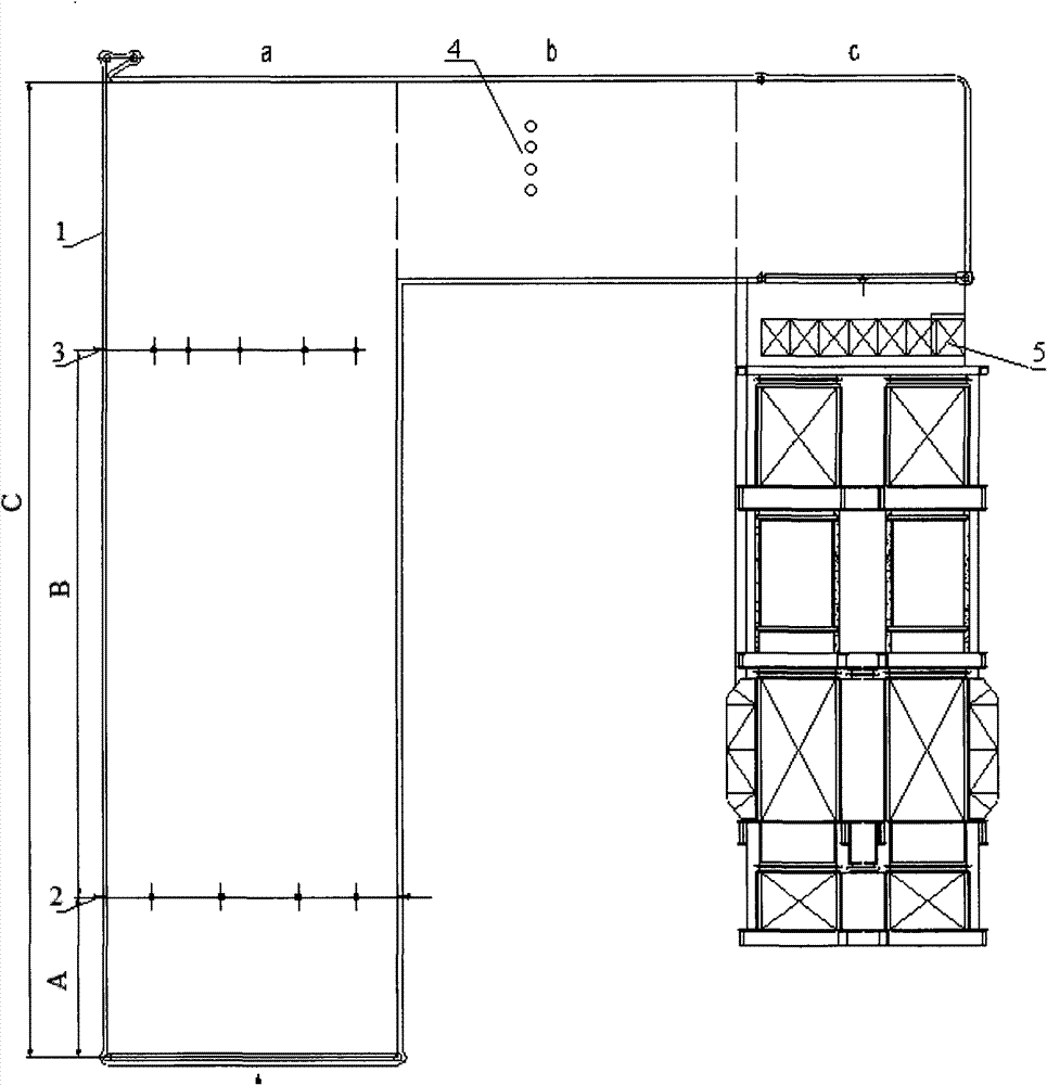
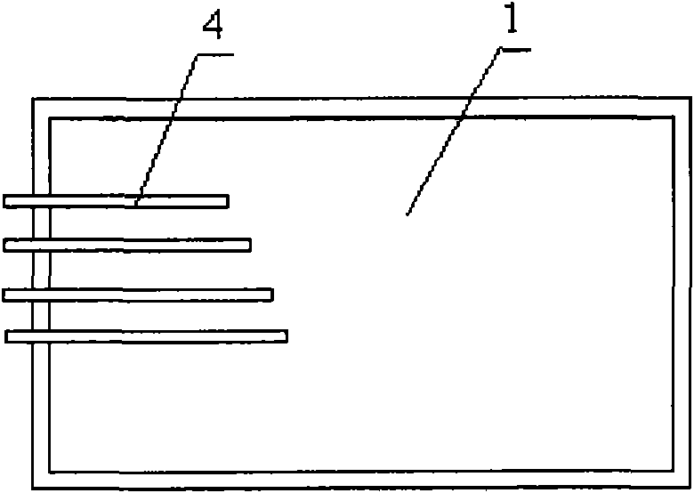
[0049] use figure 1 The flue gas denitrification equipment shown implements flue gas denitrification. The flue gas denitrification equipment includes a flue 1 and a denitration agent supply device 2, a denitrification agent supply device 3, a disturbance device 4 and a catalyst bed 5 arranged in the flue 1 in sequence. , where the flue is surrounded by 20G carbon steel pipes with a diameter of 60 mm. The cross-section of the flue is a rectangle of 10 meters x 6 meters. The 20G carbon steel pipes are equipped with demineralized water for power plant boilers. The flue has a first vertical section a, a horizontal section b, and a second vertical section c, and the two ends of the horizontal section b communicate with the upper parts of the first vertical section a and the second vertical section c respectively. A vertical section a has a height of 30 meters, a horiz...
Embodiment 2
[0056] This example is used to illustrate the flue gas denitrification method provided by the present invention.
[0057] Adopt the same flue gas denitration equipment as in Example 1 to implement flue gas denitrification, specifically, through the denitrification agent supply device 2, the urea aqueous solution with a concentration of 39% by weight is sent into the flue, and the temperature is 1000 ° C, and the flow rate is 778,000 cubic meters. m / hour of flue gas from power plant boilers (the content of nitrogen oxides is 350mg / Nm 3 ) to mix, so that the ammonia nitrogen molar ratio of the urea aqueous solution to the nitrogen oxides in the flue gas is 0.3:1, and the contact time between the flue gas and the urea aqueous solution is 1.2 seconds. And add the urea aqueous solution (at this moment, the temperature of above-mentioned first mixture is 850 ℃) that concentration is 39% by weight (at this moment, the temperature of above-mentioned first mixture is 850 ℃) in the firs...
PUM
 Abstract
Description
Claims
Application Information
 - R&D
- Intellectual Property
- Life Sciences
- Materials
- Tech Scout
- Unparalleled Data Quality
- Higher Quality Content
- 60% Fewer Hallucinations
Browse by: Latest US Patents, China's latest patents, Technical Efficacy Thesaurus, Application Domain, Technology Topic, Popular Technical Reports.
© 2025 PatSnap. All rights reserved.Legal|Privacy policy|Modern Slavery Act Transparency Statement|Sitemap|About US| Contact US: help@patsnap.com