Adjustable aerofoil and double-body aircraft aerofoil layout scheme thereof

A kind of airfoil and wing technology, applied in the aviation field, can solve the problems of limiting the flight speed of aircraft, long runways, and consuming too much fuel

Inactive Publication Date: 2011-01-12
吴新保
View PDF4 Cites 4 Cited by
  • Summary
  • Abstract
  • Description
  • Claims
  • Application Information

AI Technical Summary

Problems solved by technology

The shape of the wing of a subsonic aircraft is generally a straight wing or a swept wing. The wing thickness is large, the aspect ratio is high, the lift generated is large, and the maneuverability of the aircraft is also strong. However, when the aircraft flies at a high speed, the resistance generated It is also large, which limits the flight speed of the aircraft; the wings of supersonic aircraft using swept wings or delta wings are relatively thin, and the aspect ratio is relatively small. Although the resistance during flight is relatively small, it is beneficial to supersonic flight, but it reduces the aircraft Maneuverability, the lift generated by their wings is also small, they cannot carry a large payload when flying at low speeds, the efficiency of the aircraft is not high, it generally requires a long runway when taking off and landing at the airport, and consumes too much fuel
The variable-sweep wing layout of an aircraft that can change its wing shape in flight does not change the thinness of the wing, but it also allows the aircraft to achieve better performance at a given speed. However, to achieve these movements of the wing The required mechanisms are complex and bulky, while they also take up a lot of space, reducing efficiency and payload
When the aircraft is flying, the pressure on the leading edge of the wing is much greater than the surrounding atmospheric pressure. Because the sharp leading edge of the wing is easy to cause airflow separation, the design of the leading edge of the wing is generally round, resulting in forward motion strong resistance

Method used


Image

  • Adjustable aerofoil and double-body aircraft aerofoil layout scheme thereof
  • Adjustable aerofoil and double-body aircraft aerofoil layout scheme thereof
  • Adjustable aerofoil and double-body aircraft aerofoil layout scheme thereof

Examples


Embodiment Construction

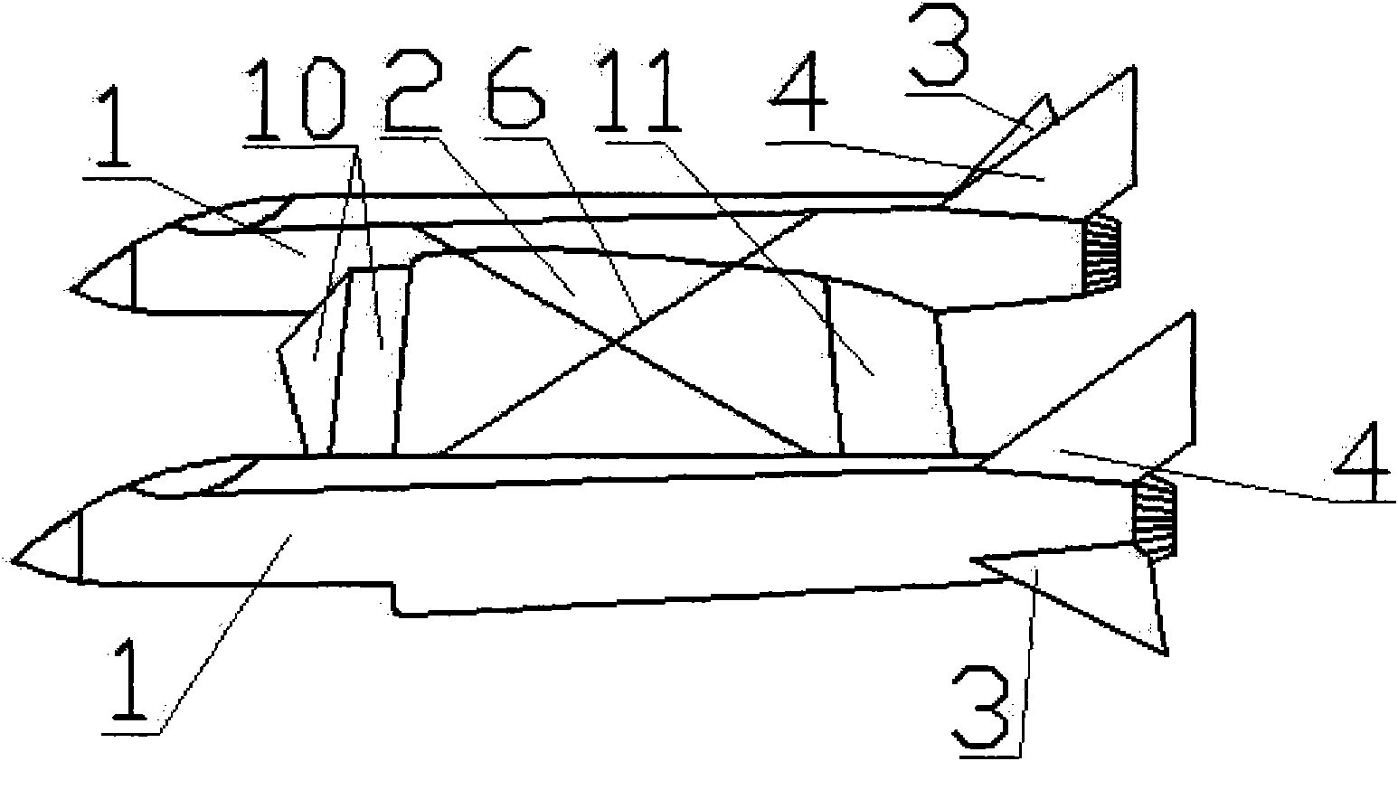
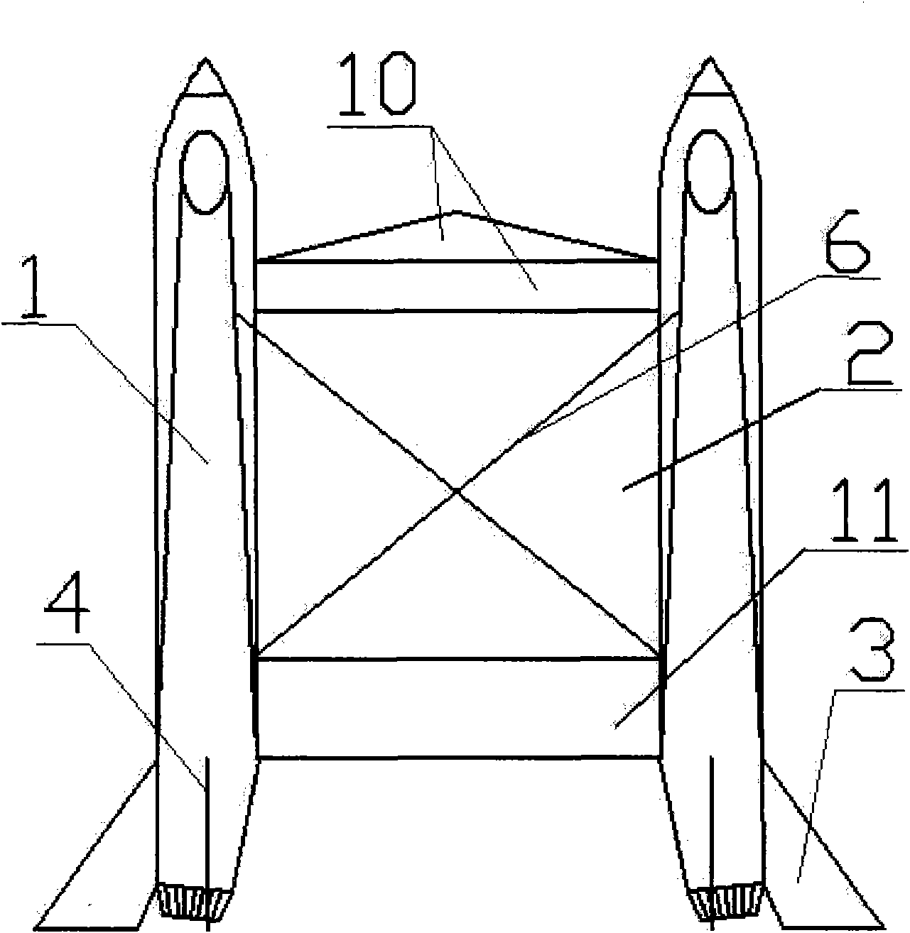
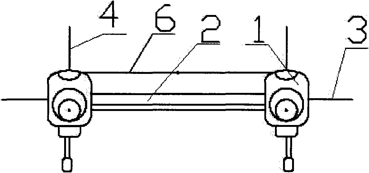
[0008] Such as figure 1 , figure 2 , image 3 Shown: the new aircraft wing layout scheme, there are two fuselages 1 arranged side by side, the overall design adopts jet engine propulsion, abdominal air intake, and advanced fly-by-wire control system at the tail of the fuselage 1, and the two fuselages 1 The lower part of the inner side of the body is connected by a rectangular main wing 2 that provides lift, and the tops of the two fuselages 1 are pulled together by wire cables 6 to prevent the two fuselages from separating outward due to gravity. The wing 2 will provide lift for the two fuselages 1, the wing chord is very long, and the two chords of the rectangular main wing 2 are connected with the fuselage 1, although the aspect ratio is very small, because there is no exposed wing end, it can also Effectively reduce the induced drag. Since the two fuselages are relatively far apart, in order to prevent the aircraft from rotating when only one engine is working in case o...


PUM


Abstract

The invention discloses an adjustable aerofoil and a double-body aircraft aerofoil layout scheme thereof. The double-body aircraft aerofoil layout scheme is as follows: two fuselages are arranged side by side and the insides of the two fuselages are connected through a rectangular main aerofoil. The used rectangular main aerofoil is characterized in that the outer flexible aerofoil skin is supported by a plurality of inner rollers which can rotate to drive the flexible aerofoil skin, thus initiatively increasing the relative speed between the upper and lower surfaces of the aerofoil and the air flow; and the positions of the rollers can be adjusted to change the airfoil profile and adapt to different flight speeds. Compared with the existing fixed wing aircraft, the aircraft with the adjustable aerofoils of the invention has higher weight capacity and smaller floor space and has less resistance in the high-speed flight; and during the low-speed flight, the aircraft has the advantages of lower level flight speed, safer ultra-short take-off and landing and the like.

Description

Technical field [0001] The invention relates to the field of aviation, in particular to a novel adjustable airfoil wing and a catamaran wing layout scheme for its application. technical background [0002] As we all know, the principle of lift generation of fixed-wing aircraft is that the upper surface of the wing protrudes and the lower surface is slightly flat, so that when passing through the air, the airflow velocity difference between the upper and lower surfaces is passively used to generate lift. Known fixed-wing aircraft generally has subsonic aircraft and supersonic aircraft, and subsonic aircraft is divided into low speed aircraft and high subsonic aircraft. The position of the thickest part of the airfoil section of various existing aircraft is different at the position of the wing chord, and the position of the maximum thickness of the wing section of a subsonic aircraft is about 25-40% of the distance between the leading edge and the trailing edge. Where the ma...

Claims


Application Information

Patent Timeline
Patent Type & Authority Applications(China)
IPC IPC(8): B64C3/38B64C3/20
Inventor 吴新保
Owner 吴新保
Why Eureka
Try Eureka