Liquid phase fluorination reaction device

A liquid-phase fluorination and reaction device technology, which is applied in organic chemistry, halogen substitution preparation, etc., can solve the problems of inconspicuous catalytic effect, slow reaction speed, poor mass transfer and heat transfer effects, etc., to improve mass transfer effect, The effect of reducing the volume and speeding up the reaction speed

Inactive Publication Date: 2013-05-08
XIAN MODERN CHEM RES INST
View PDF2 Cites 0 Cited by
  • Summary
  • Abstract
  • Description
  • Claims
  • Application Information

AI Technical Summary

Problems solved by technology

In the case of no stirring and low reaction temperature, the mass transfer and heat transfer effects are poor, the catalytic effect is not obvious, and the reaction speed is slow

Method used


Image

  • Liquid phase fluorination reaction device
  • Liquid phase fluorination reaction device
  • Liquid phase fluorination reaction device

Examples


Embodiment 1

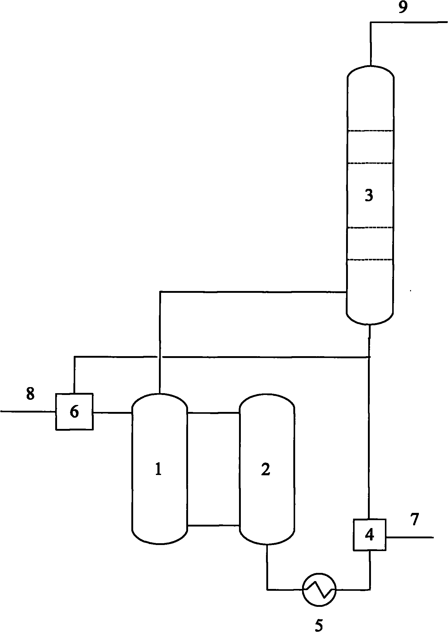
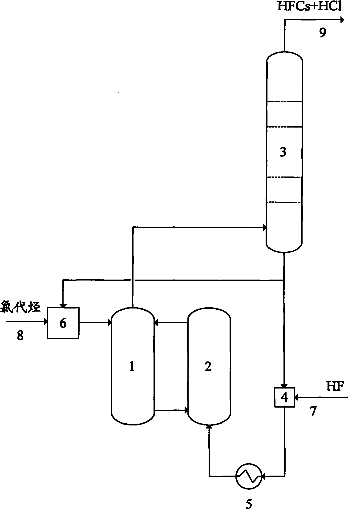
[0022] Refer to attached figure 1 , 3 The present invention is further described in detail.

[0023] First the SbCl 5The liquid phase fluorination catalyst is added to the liquid phase fluorination reactor; fresh HF enters the high temperature from the bottom feed port after being preheated by the HF feed mixer (4) and the HF preheater (5) through the HF feed pipe (7). Reaction zone (2), and enters low-temperature reaction zone (1) from the upper outlet of high-temperature reaction zone (2), HF enters reflux tower (3) by the top outlet of low-temperature reaction zone (1), as reflux tower A part of the bottom fraction of (3) is circulated to the high-temperature reaction zone (2) through the HF feed mixer (4), and another part is circulated to the low-temperature reaction zone (1) through the chlorinated hydrocarbon feed mixer (6). By controlling the outlet temperature of the HF preheater (5) and the flow rate of HF, the temperature of the low-temperature reaction zone (1) ...

Embodiment 2

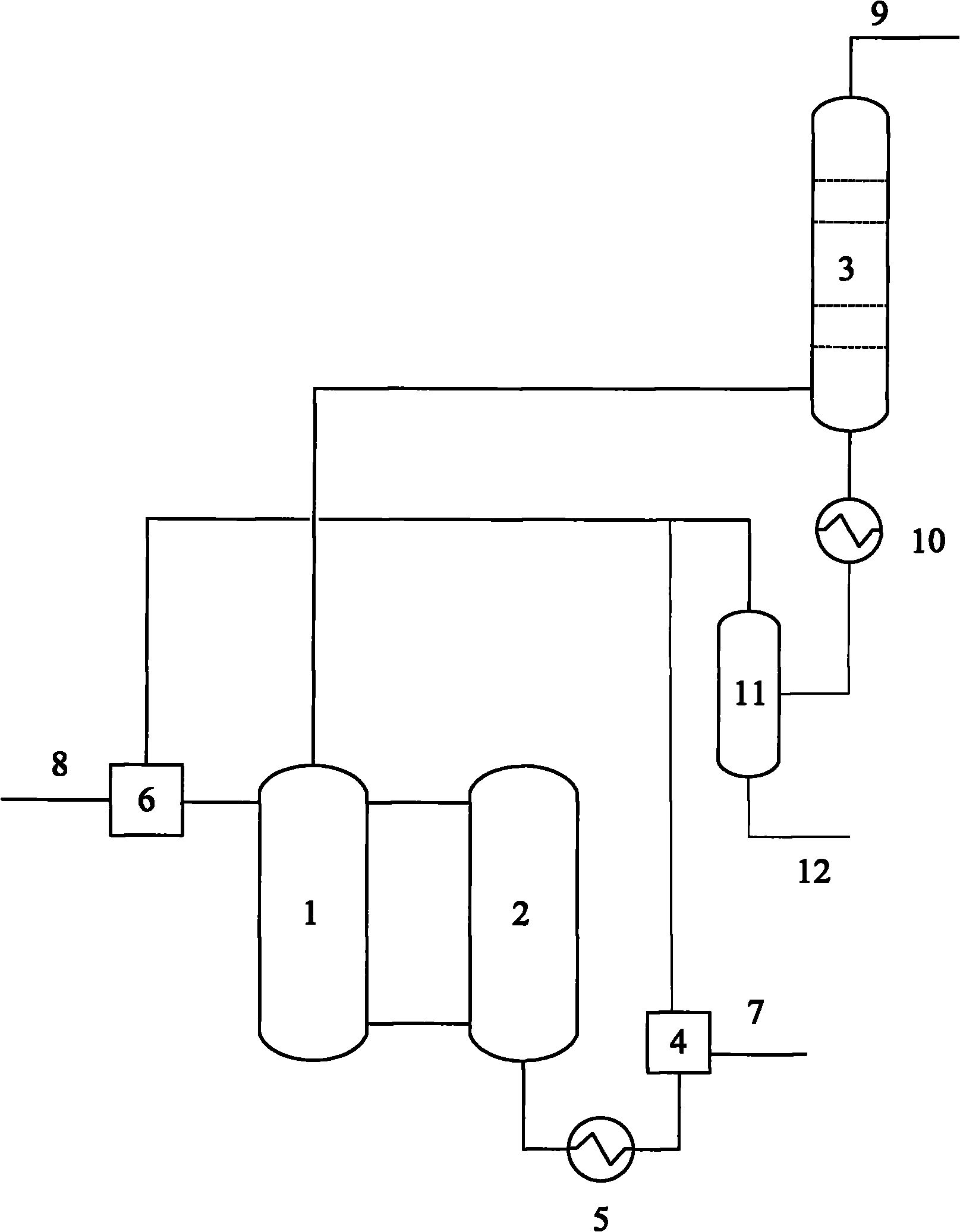
[0027] Refer to attached figure 2 , 4 The present invention is further described in detail.

[0028] First the SbCl 5 The liquid phase fluorination catalyst is added to the liquid phase fluorination reactor; fresh HF enters the high temperature from the bottom feed port after being preheated by the HF feed mixer (4) and the HF preheater (5) through the HF feed pipe (7). Reaction zone (2), and enters low-temperature reaction zone (1) from the upper outlet of high-temperature reaction zone (2), HF enters reflux tower (3) by the top outlet of low-temperature reaction zone (1), as reflux tower The bottom fraction of (3) enters the phase separator (11) after being cooled by the cooler (10), a part is circulated to the high temperature reaction zone (2) through the HF feed mixer (4), and the other part is mixed through the chlorinated hydrocarbon feed The device (6) is recycled to the low temperature reaction zone (1). By controlling the outlet temperature of the HF preheater (...


PUM


Abstract

The invention provides a liquid phase fluorination reaction device, which comprises a low-temperature reaction area (1), a high-temperature reaction area (2), a backflow tower (3), an HF feed mixer (4), an FH pre-heater (5), a chlorohydrocarbon feed mixer (6), an HF feeding pipe (7), a chlorohydrocarbon feeding pipe (8) and a discharge pipe (9) at the top of the backflow tower, wherein both the upper and lower parts of the low-temperature reaction area (1) are communicated with the high-temperature reaction area (2), a top outlet is communicated with a lower gas feeding inlet of the backflow tower (3); a top discharge port of the backflow tower is connected with the product discharge pipe (9), while a bottom discharge port is communicated with the HF feed mixer (4) and the chlorohydrocarbon feed mixer (6); the HF feed mixer (4) is communicated with the bottom feeding port of the high-temperature reaction area (2) through the FH pre-heater (5); the HF feed pipe (7) is connected with the feeding port of the HF feeding mixer (4); and the chlorohydrocarbon feeding pipe (8) is connected with the low-temperature reaction area (1) through the chlorohydrocarbon feed mixer (6). The liquid phase fluorination reaction device is mainly applied to a twp-step liquid phase fluorination reaction process for synthesizing hydrofluorocarbon.

Description

technical field [0001] The invention relates to a liquid-phase fluorination reaction device, which is suitable for the two-step liquid-phase fluorination reaction process of synthesizing hydrofluorocarbons (HFCs). Background technique [0002] Under the action of metal chloride catalysts, the synthesis of hydrofluorocarbons by the liquid-phase fluorination reaction of HF and chlorinated hydrocarbons is the main method for industrially preparing hydrofluorocarbons. The liquid-phase fluorination reaction to synthesize 1,1,1,3,3-pentafluoropropane, 1,1,1,3,3-pentafluorobutane and other hydrofluorocarbons with more than 3 carbon atoms is a multi-step reaction, the traditional Single-stage continuous fluorination reactors cannot meet the needs of two-step liquid-phase fluorination reactions for the synthesis of hydrofluorocarbons. Moreover, the reaction system formed by metal chlorides and HF is highly corrosive, and the corrosiveness increases with the increase of temperature. ...

Claims


Application Information

Patent Timeline
Patent Type & Authority Patents(China)
IPC IPC(8): C07C17/20C07C19/08C07C19/10
Inventor 张伟吕剑寇联岗曾纪珺袁俊杜咏梅马洋博李凤仙
Owner XIAN MODERN CHEM RES INST
Why Eureka
Try Eureka