Photoactivation positioning microscopic imaging system based on micronano optical fiber evanescent field illuminator

A light-activated positioning, micro-nano fiber technology, used in fluorescence/phosphorescence, instruments, scientific instruments, etc., can solve the problems of difficult to adjust the optical path, increase the system cost, and cannot detect the biological function of the upper surface and side of the cell, etc. Simple adjustment and cost reduction effect

Inactive Publication Date: 2012-05-30
HUAZHONG UNIV OF SCI & TECH
View PDF0 Cites 0 Cited by
  • Summary
  • Abstract
  • Description
  • Claims
  • Application Information

AI Technical Summary

Problems solved by technology

[0006] Existing light-activated positioning microscopy imaging systems generally use large numerical aperture objective lenses to generate evanescent fields for illumination. The disadvantages are: 1) the large numerical aperture increases the cost of the system; 2) the overlapping of the illumination optical path and the detection optical path is not easy to adjust Optical path; 3) According to the principle of total internal reflection, only the lower surface of adherent cells can be detected, but the upper surface and sides of cells with biological functions cannot be detected

Method used


Image

  • Photoactivation positioning microscopic imaging system based on micronano optical fiber evanescent field illuminator
  • Photoactivation positioning microscopic imaging system based on micronano optical fiber evanescent field illuminator
  • Photoactivation positioning microscopic imaging system based on micronano optical fiber evanescent field illuminator

Examples


Embodiment 1

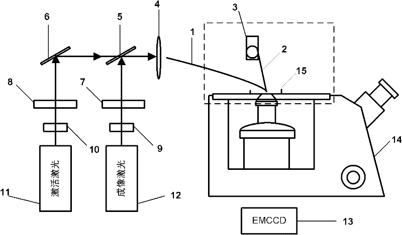
[0018] Embodiment 1: The super-resolution microscopic imaging of biological cells is realized by using a light-activated localization microscopic imaging system based on a micro-nano optical fiber evanescent field illuminator.

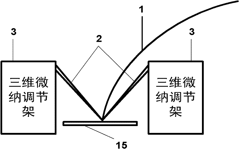
[0019] Such as figure 1 Schematic diagram of the system structure for super-resolution microscopic imaging of biological cells using the light-activated localization microscopic imaging system based on micro-nano optical fiber evanescent field illuminator. The experimental sample is the β subunit of the BK channel of HEK293 cells labeled with fluorescent protein Dronpa. The wavelength of the activation laser is 405nm, and the wavelength of the imaging laser is 473nm. The reflective mirror 6 and the dichroic mirror 5 adjust the propagation directions of the activation light and the imaging light to be the same. The lens 4 is used to couple the activation light and imaging light into the micro-nano fiber evanescent field illuminator 1 . The three-dime...


PUM

PropertyMeasurementUnit
diameteraaaaaaaaaa
diameteraaaaaaaaaa
lengthaaaaaaaaaa

Abstract

The invention relates to a photoactivation positioning microscopic imaging system based on a micronano optical fiber evanescent field illuminator. In the invention, an activated laser emitted by an activation laser device sequentially passes through a neutral filter, a shutter and a controller thereof, a reflector, a dichroiscope and a lens and then enters the nano optical fiber evanescent field illuminator; an imaging laser emitted by an imaging laser device sequentially passes through the neutral filter, the shutter and the controller thereof, the dichroiscope and the lens and then enters the nano optical fiber evanescent field illuminator; and a nano optical fiber probe is installed on a three-dimensional nano adjusting bracket, the nano optical fiber section of the nano optical fiber evanescent field illuminator is placed in a sample reservoir of an inverted fluorescent microscope, the nano optical fiber evanescent field illuminator is pushed by the nano optical fiber probe so as to regulate the position of the nano optical fiber evanescent field illuminator, and a detector EMCCD (Electronic Multiplier Charge Coupled Device) collects a fluorescent signal collected by an objective of the inverted fluorescent microscope. In the invention, an illumination light path is separated from an imaging light path, therefore, the light path adjustment is simpler; the system cost is reduced without using the objective with a large numerical aperture; and all surfaces of a cell are imaged through controlling the three-dimensional position of the nano optical fiber evanescent field illuminator.

Description

technical field [0001] The invention relates to a photoactivation positioning microscopic imaging system based on a micro-nano optical fiber evanescent field illuminator, especially a photoactivation positioning microscopic imaging system that can provide large illumination energy and perform multi-directional illumination imaging on samples . Background technique [0002] Far-field optical fluorescence microscopy has the advantages of non-contact, non-destructive and capable of detecting the interior of samples, etc., and it has always been a commonly used observation tool in life sciences. However, due to the existence of the diffraction limit, even if the numerical aperture is increased by using an oil immersion objective lens, the lateral resolution of the traditional wide-field optical microscope is about 200nm, which cannot be used to observe the dynamic and structural characteristics of intracellular molecular scale. In recent years, light-activated localization micr...

Claims


Application Information

Patent Timeline
Patent Type & Authority Patents(China)
IPC IPC(8): G01N21/64
CPCG01N21/648G01N21/6458
Inventor 黄振立曾绍群付玲吕晓华骆清铭
Owner HUAZHONG UNIV OF SCI & TECH
Why Eureka
Try Eureka