Liquid metal cooling and directional condensing equipment with tin boiler stirrer

A liquid metal cooling and stirring device technology, applied in the direction of self-solidification, crystal growth, chemical instruments and methods, etc., can solve the problems of prolonging the production cycle, reducing the heat preservation effect, and cumbersome operation, so as to solve the problem of overflow and speed up heat transfer , the effect of uniform temperature

Inactive Publication Date: 2011-01-26
SHENYANG RES INST OF FOUNDRY
View PDF6 Cites 8 Cited by
  • Summary
  • Abstract
  • Description
  • Claims
  • Application Information

AI Technical Summary

Problems solved by technology

[0006] 1. Discharge the floating heat insulation baffle on the surface of the liquid metal molten pool, resulting in the accumulation of floating heat insulation baffles, reducing the heat preservation effect and uneven heat preservation temperature;
[0007] 2. Make the temperature of the liquid metal cooling medium around the mold rise sharply, reduce the heat transfer effect and the temperature gradient of the solidification front of the alloy in the mold;
[0008] 3. Cause the liquid metal cooling medium to rise, enter the holding furnace, damage the heating element, and cause the liquid cooling medium to volatilize
But this stirring device cannot stir the liquid metal cooling medium
Chinese patent (Patent No.: CN 2808362Y) discloses a device for producing directional solidified castings. This device can only stir liquid metal tin, but not the floating insulation baffle
This method is cumbersome to operate and prolongs the production cycle

Method used


Image

  • Liquid metal cooling and directional condensing equipment with tin boiler stirrer
  • Liquid metal cooling and directional condensing equipment with tin boiler stirrer

Examples


Embodiment Construction

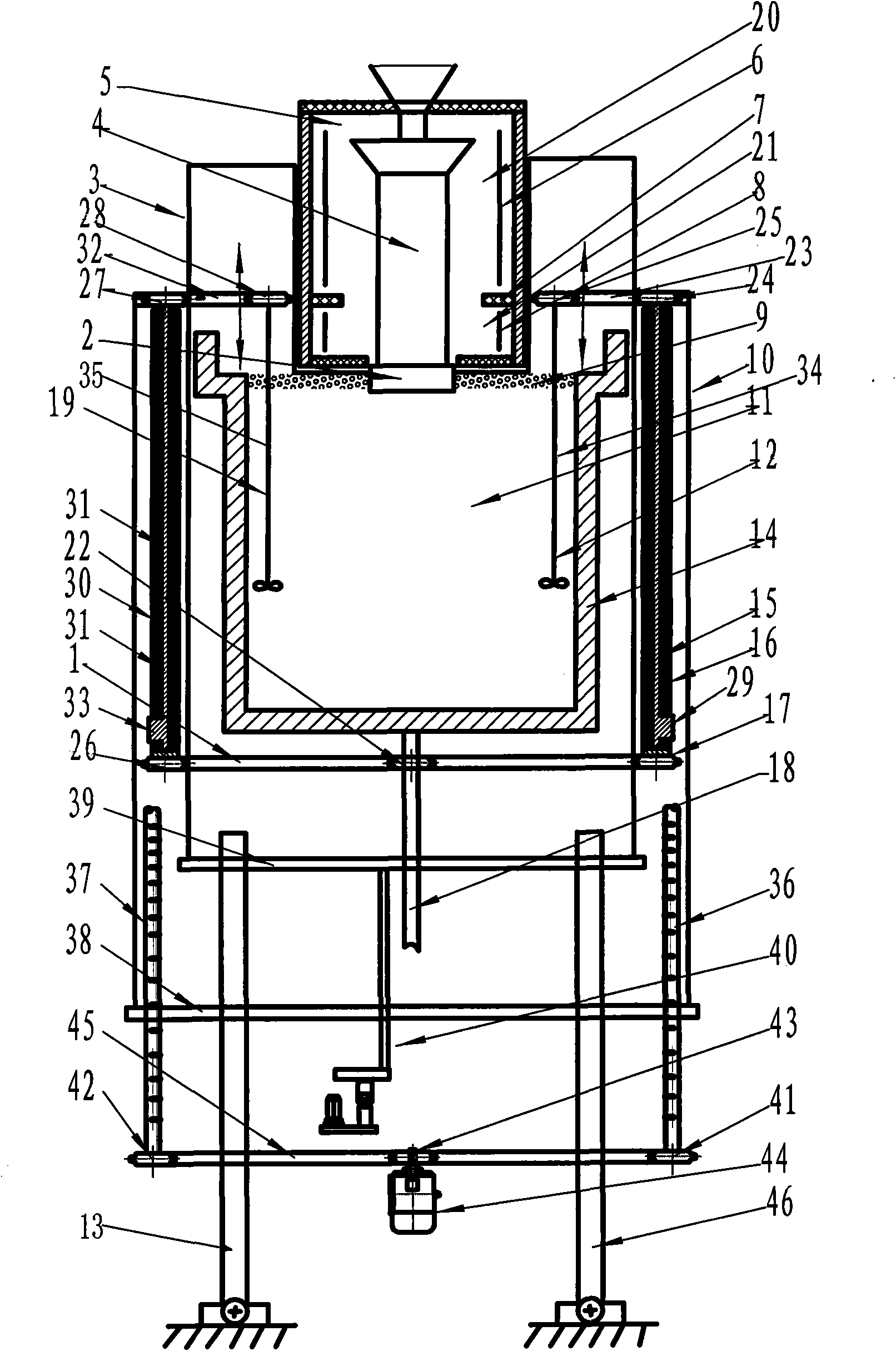
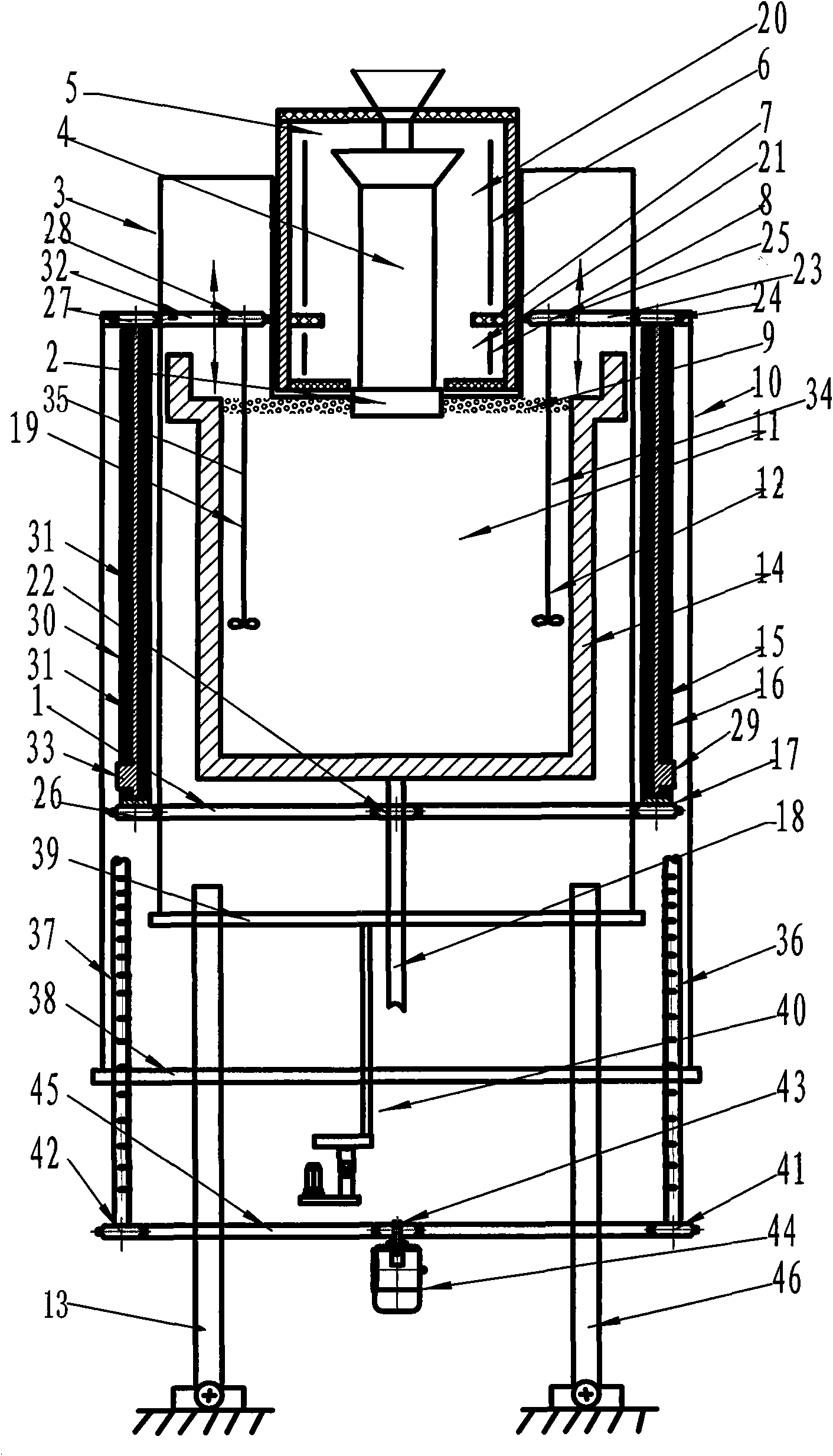
[0024] A liquid metal cooling and directional solidification equipment with a tin pot stirring device, including a mold heating and holding furnace 5, a ceramic mold 4, a chilling tray 2, a pull bracket 3, a container 14, a floating heat insulation baffle 9, and a A stirring device 12, a second stirring device 19 and a stirring device driving mechanism;

[0025] The inner wall of the mold heating and holding furnace 5 is fixed with an annular heat insulating baffle 7, and the annular heat insulating baffle 7 divides the inner space of the casting mold heating and holding furnace 5 into an upper heating zone 20 and a lower heating zone 21. A first heater 6 is set in the zone 20, and when the first heater 6 works, the upper heating zone 20 is heated to 1500-1550°C and kept at 1500-1550°C; a second heater 8 is set in the lower heating zone 21, The second heater 8 heats the lower heating zone 21 to 1550-1650°C;

[0026] The ceramic mold 4 is installed in the mold heating and hold...


PUM


Abstract

The invention discloses liquid metal cooling and directional condensing equipment with a tin boiler stirrer, which comprises a mould heating and insulating furnace, a ceramic mould, a chilling tray, a drawing bracket, a container, a floating insulation baffle, a first stirrer, a second stirrer and a stirrer drive mechanism, wherein an upper heating area and a lower heating area are reserved in the mould heating and insulating furnace, the ceramic mould is arranged in the mould heating and insulating furnace, and the chilling tray is connected with the ceramic mould and driven by the drawing bracket to move up and down; the container is arranged below the mould heating and insulating furnace and filled with liquid metal tin, and the floating insulation baffle is arranged on the liquid surface of the liquid metal tin; and the first and second stirrers capable of rising and descending are symmetrically arranged in the container. The liquid metal cooling and directional condensing equipment with the tin boiler stirrer solves the problem of overflowing of the liquid metal tin and prevents the liquid surface of the liquid metal tin from rising and contacting the heating furnace; and due to vertical movement of the stirrers, the heat exchange of the liquid metal tin is speeded up, so that the temperature of the liquid metal tin is uniform.

Description

technical field [0001] The invention relates to a liquid metal cooling directional solidification device with a tin pot stirring device, in particular to a tin pot stirring device suitable for the directional solidification device for manufacturing large-scale gas turbine column crystal blades. Background technique [0002] Due to the development of aviation, aerospace and ground gas turbine power generation technology, the temperature of the gas inlet before the turbine of the power mechanical gas turbine used in these fields is continuously increasing, which requires the temperature resistance of the turbine blades to continuously increase. The directional and single crystal blades eliminate the transverse grain boundary perpendicular to the stress axis, and the grain direction is parallel to the stress direction acting on the blade, which cuts off the root cause of failure occurring at the grain boundary perpendicular to the stress direction, and the temperature resistance...

Claims


Application Information

Patent Timeline
Patent Type & Authority Applications(China)
IPC IPC(8): B22D27/04C30B11/00
Inventor 娄延春于波刘孝福苏贵桥
Owner SHENYANG RES INST OF FOUNDRY
Why Eureka
Try Eureka