

Broken rail real-time detection device and detection method thereof
A detection device and a technology for rail breakage, which are used in transportation and packaging, railway vehicle shape measuring instruments, and railway car body components, etc., can solve the problems of inability to perform real-time rail break detection and hidden dangers in operational safety, and increase the complexity of the equipment. Strong anti-traction backflow interference ability, small effect of primary parameters and environmental factors
- Summary
- Abstract
- Description
- Claims
- Application Information
AI Technical Summary
Problems solved by technology
Method used
Image

Examples
Embodiment 1
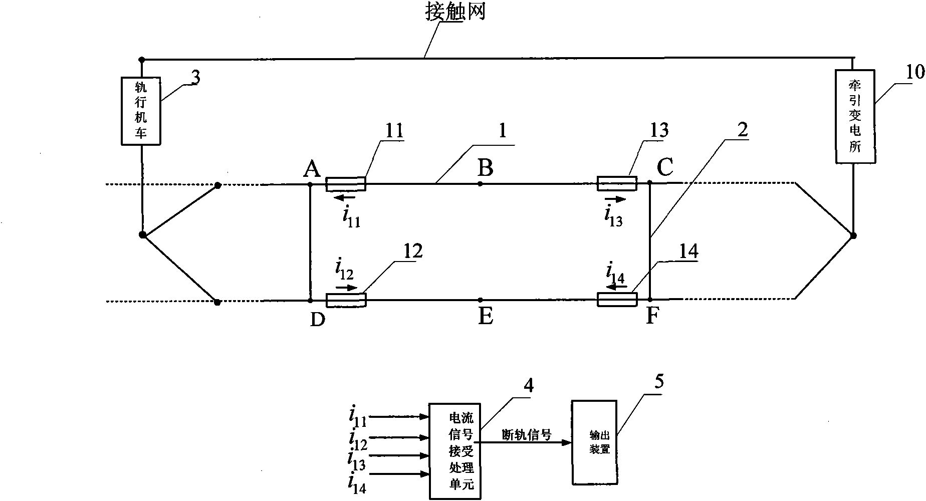
[0035] Example 1: see figure 1 , a broken rail detection device, comprising two rails 1 of a rail locomotive, a pair of electrical short wires 2 (AB, CD) are arranged between the two rails, a pair of electrical short wires 2 (AB, CD) CD) and the rail 1 encircle an electrical isolation unit; four current sensors 11, 12, 13, 14 are arranged on the rail of the electrical isolation unit, and the described current sensors 11, 12, 13, 14 and the current signal receiving and processing unit 4 is electrically connected and outputs the broken rail signal to the output device 5. The current signal receiving and processing unit includes a filter, a microprocessor, a programmable logic controller, a logic module, and the like.
[0036] The distance between two electrical short wirings is 2-4km.
[0037] The current sensor is mounted on the rail near the end of the electrical short connection.
[0038] When the rail locomotive 3 travels on the electrified railway, or stops on the railwa...
Embodiment 2
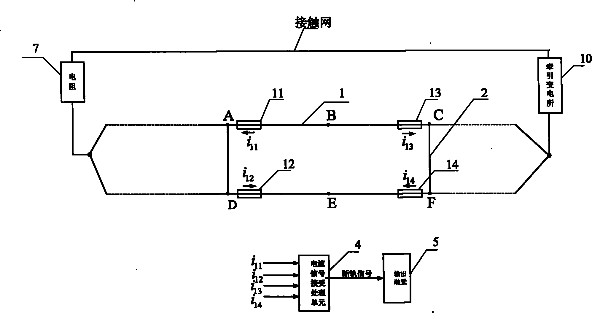
[0043] Example 2, see figure 2 , same as Embodiment 1, the difference is that it also includes a resistor 7, and the resistor is arranged between the catenary and the steel rail at the end of the power supply section of the traction substation.
[0044] If there is no locomotive running on the electrified railway, or when it is parked on the railway, there is no traction backflow on the rail between the traction substation and the locomotive. At this time, a resistor can be connected between the catenary and the rail at the end of the power supply section of the traction substation. The principle for determining the size of the resistance is to consume the least power under the premise of being able to detect broken rails (equivalent to the equivalent resistance of an unloaded running locomotive). In this way, current flows on the rail between the resistor and the traction substation. The change of the current signal detected by the sensor with the state of the rail is the ...
Embodiment 3
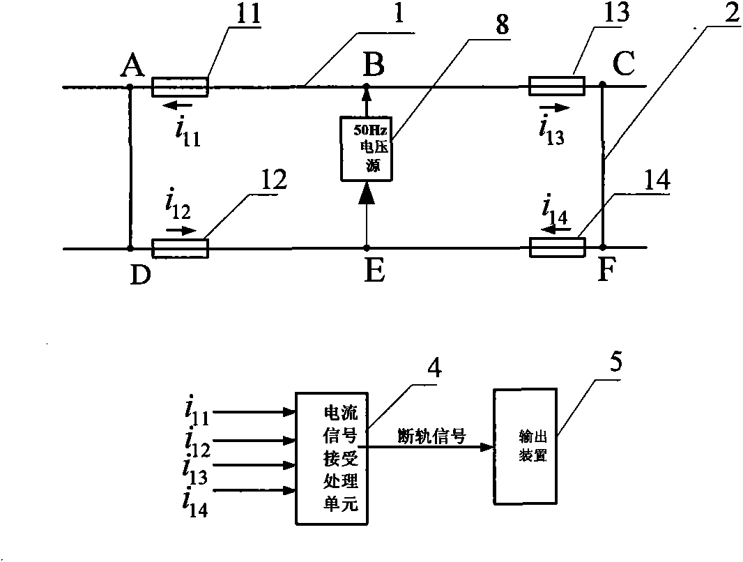
[0045] Embodiment 3: see image 3 , the same as that of Embodiment 1, the difference is that it also includes a voltage source 8, and the voltage source is arranged between the two steel rails at the middle position of the electrical isolation unit. The frequency of the voltage source may be 50 Hz.
[0046] In the case of no traction return (such as on non-electrified railways, or there are no locomotives on electrified railways), current can be generated on the rails by means of an external power supply.
[0047] Table 2 gives the image 3 The current signal of the medium current sensor in different rail states (when the track is complete, the current of each sensor is equal and equal to 1).
[0048] The sensor current when the 250Hz voltage source acts on the table
[0049]
[0050] It can be seen from Table 2 that the current signals of the four current sensors and their combinations have obvious differences in different rail states, so it can be judged whether ...
PUM
 Abstract
Description
Claims
Application Information