
Non-air power driven sucker device

A power-driven, airless technology, applied in the direction of suction cups, connecting components, mechanical equipment, etc., can solve the problems of suction cup products without structure, increase production costs, noise pollution, etc., to reduce power consumption, reduce equipment costs, and eliminate noise pollution effect

Inactive Publication Date: 2011-01-26
九豪精密陶瓷(昆山)有限公司
View PDF5 Cites 3 Cited by
  • Summary
  • Abstract
  • Description
  • Claims
  • Application Information

AI Technical Summary

Problems solved by technology

The control valve of this method passes the compressed air from the air pump through a nozzle to form a high-speed jet, which takes away the air in the suction cup to form a negative pressure, so that the suction cup can hold the object; the use of this suction cup device is relatively convenient. The cost is relatively low, but its disadvantage is that it needs to maintain a high-speed jet to form negative pressure, so the waste of air source is serious, and it also needs to be equipped with an air pump and its control system
[0006] As mentioned above, the vacuum chuck in the prior art is usually a pneumatic component, which needs to be equipped with aerodynamic drive to realize its function, so it will cause additional cost input and power consumption of aerodynamic equipment for the user. , thus greatly increasing the production cost
At the same time, the use of aerodynamic drive will generate noise pollution, including the noise generated by the compressor used to generate aerodynamic force during operation, and the pneumatic control valve used to generate temporary negative vacuum in the enclosed space when controlling the sucker to suck the object. exhaust noise etc.
[0007] This shows that the above-mentioned existing sucker device obviously still has inconvenience and defects in its structure and use, and needs to be further improved urgently.
In order to solve the above-mentioned problems existing in the prior art, the related industry has tried their best to find a solution, but no suitable design has been developed for a long time, and the general suction cup products do not have a suitable structure to solve the above-mentioned problems.

Method used


Image

  • Non-air power driven sucker device
  • Non-air power driven sucker device
  • Non-air power driven sucker device

Examples


Embodiment Construction

[0018] Hereinafter, the present invention will be described as exemplary preferred embodiments with reference to the accompanying drawings. The structures shown in the exemplary embodiments and diagrams are only preferred embodiments of the present invention, and do not fully represent the technical spirit of the present invention. In the following description, the same elements in different drawings will be denoted by the same reference numerals. In addition, the directional terms mentioned in the following descriptions, such as "upper", "lower", "inner", "outer", "top", "bottom", etc., are only used to refer to the directions in the attached drawings. Illustrative, not limiting of the invention. Also, in the following description, detailed explanations of known related functions and structures may be omitted to avoid unnecessarily obscuring the subject matter of the present invention.

[0019] Relevant detailed description and technical contents of the present invention ar...


PUM


Abstract

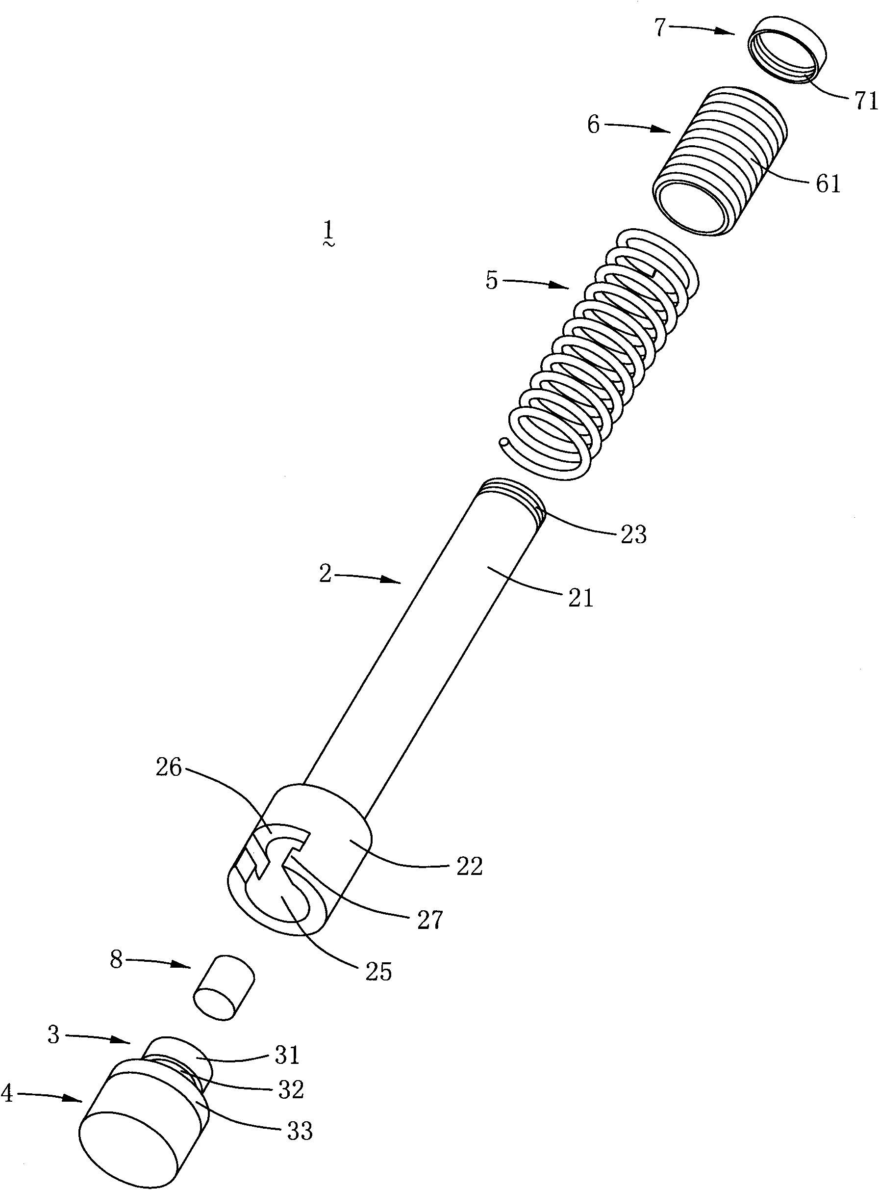
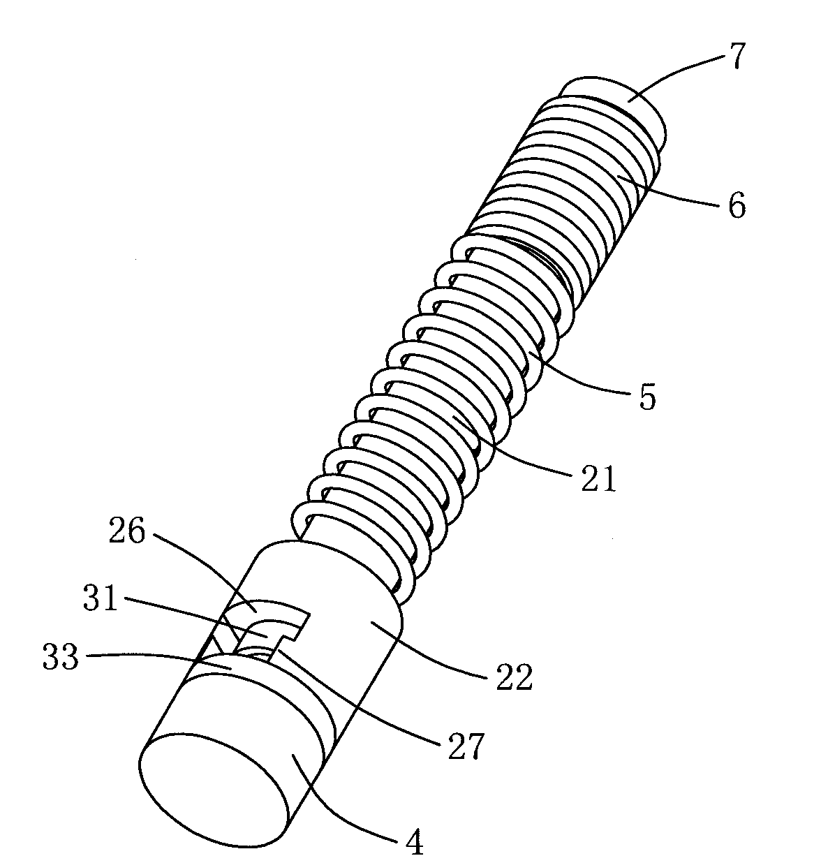
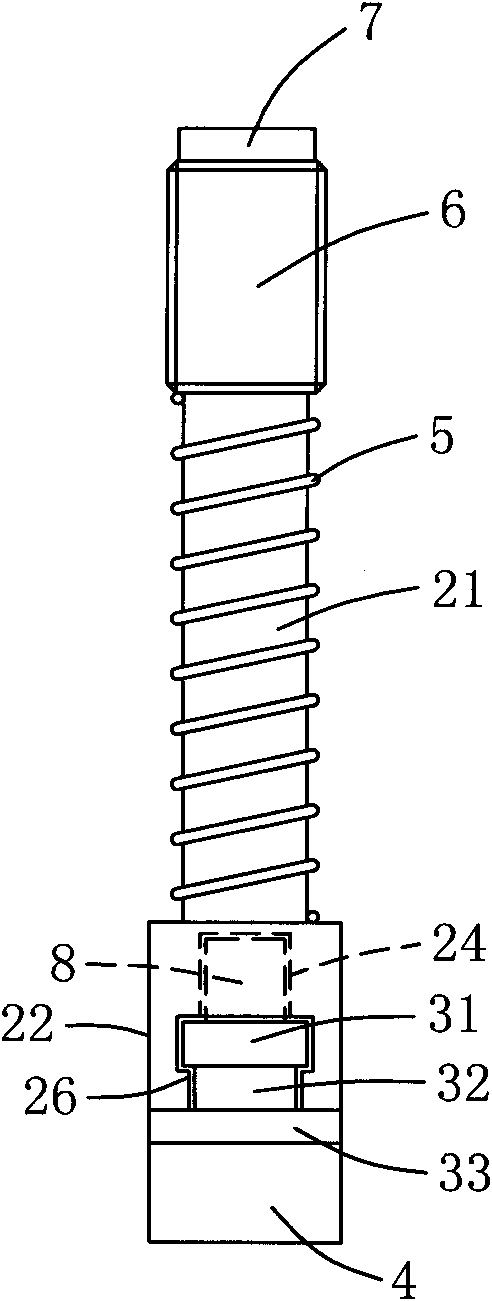
The invention relates to a non-air power driven sucker device which comprises a guide rod, a joint, a sucker, a spring and a liner bushing. The guide rod comprises a rod part and a joint part. The joint part is provided with a clamping port used for being clamped into the joint and a joint accommodating hole communicated with the clamping port. A pushing and stopping part is arranged at the free end of the rod part. The sucker is a solid sucker made of silica gel, is arranged at the bottom part of the joint and extends out of the joint part of the guide rod. The spring is assembled on the outer peripheral surface of the rod part of the guide rod and pushed and connected with the joint part of the guide rod. The liner bushing is assembled on the outer peripheral surface of the rod part of the guide rod by being adjacent to the spring, and pushed and stopped at the pushing and stopping part of the rod part with the help of elasticity of the spring. The sucker device can realize adsorption and transportation of objects without being driven by air power, further greatly reduce the equipment cost input, reduce consumption of electrical energy and eliminate noise pollution.

Description

technical field [0001] The invention relates to a suction cup device for absorbing objects, in particular to a suction cup device driven without aerodynamic force. Background technique [0002] At present, there are two main types of sucker devices in the industry that use adsorption action to grasp and release objects: one is a vacuum chuck that uses negative pressure to absorb objects, and the other uses electromagnets to absorb ferromagnetic objects. suction device. Among them, the latter needs to provide continuous electric energy to maintain the magnetism of the suction cup, so the energy consumption is relatively high. In addition, in addition to heat generation and electrical safety issues, once a power failure or circuit failure occurs, the grasped objects are easy to fall, so it is not safe to use. If the permanent magnet is simply used to adsorb the ferromagnetic object, it is difficult to control the presence or absence of magnetism, so although it is easy to gr...

Claims


Application Information

Patent Timeline
Patent Type & Authority Applications(China)
IPC IPC(8): F16B47/00
Inventor 吴王祺
Owner 九豪精密陶瓷(昆山)有限公司
Learn More