
Gas-liquid component high chamber-pressure large-range variable working condition combustor

A large-scale, variable-working-condition technology, applied to burners, lighting and heating equipment, etc., can solve problems such as low thrust, insufficient ability to change working conditions in a small range, low chamber pressure, etc., to achieve guaranteed cooling, good performance, and simplified structure and the effect of the process

Active Publication Date: 2011-01-26
NO 11 INST OF NO 6 ACADEMY OF CHINA AEROSPACE SCI & TECH
View PDF12 Cites 9 Cited by
  • Summary
  • Abstract
  • Description
  • Claims
  • Application Information

AI Technical Summary

Problems solved by technology

[0003] The purpose of the present invention is to provide a new gas-liquid component burner with high chamber pressure and wide range of variable working conditions, which solves the technical problems of the existing gas-liquid component burner with low chamber pressure, low thrust, and insufficient ability to change working conditions in a small range

Method used


Image

  • Gas-liquid component high chamber-pressure large-range variable working condition combustor
  • Gas-liquid component high chamber-pressure large-range variable working condition combustor
  • Gas-liquid component high chamber-pressure large-range variable working condition combustor

Examples


Embodiment Construction

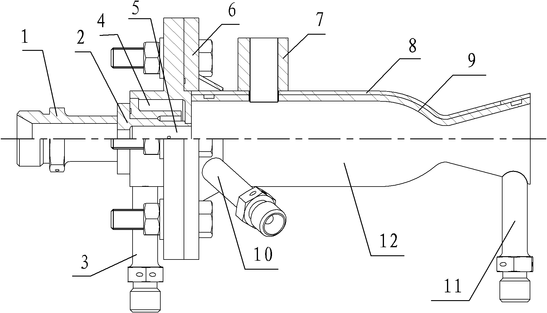
[0028] figure 1 Shown is a half-section structure diagram of a gas-liquid component high-chamber-pressure variable-range burner of the present invention, the burner is composed of an injector and a nozzle, and the injector and the nozzle are connected by a flange 6 . The volume of the oxidant liquid collection chamber formed by the oxidant inlet pipe 1 and the gas-liquid two-component nozzle 2 should be as small as possible. The baffles in the combustion chamber allow for increased combustion fluid velocity, thereby cooling the injector face plate.

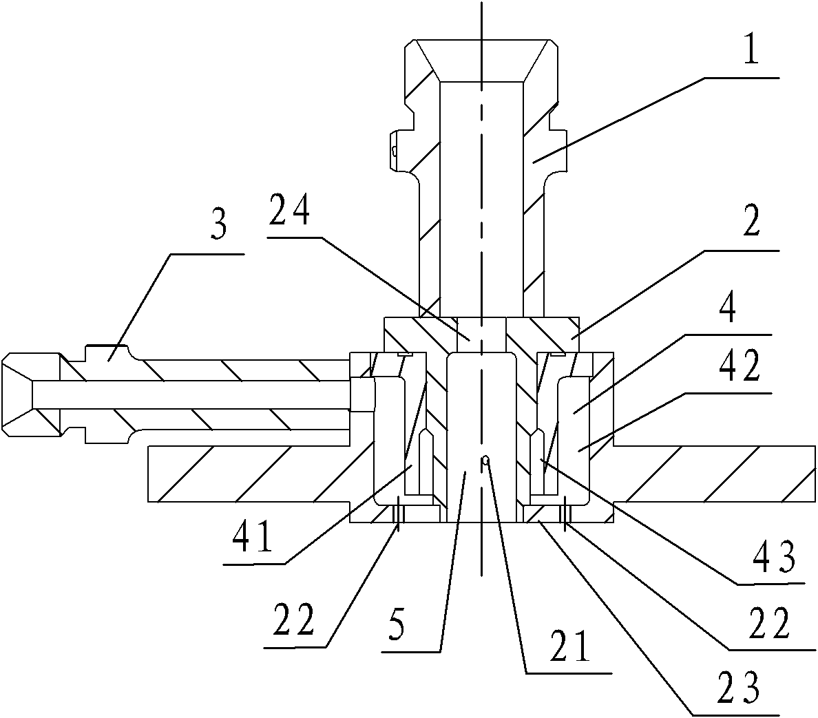
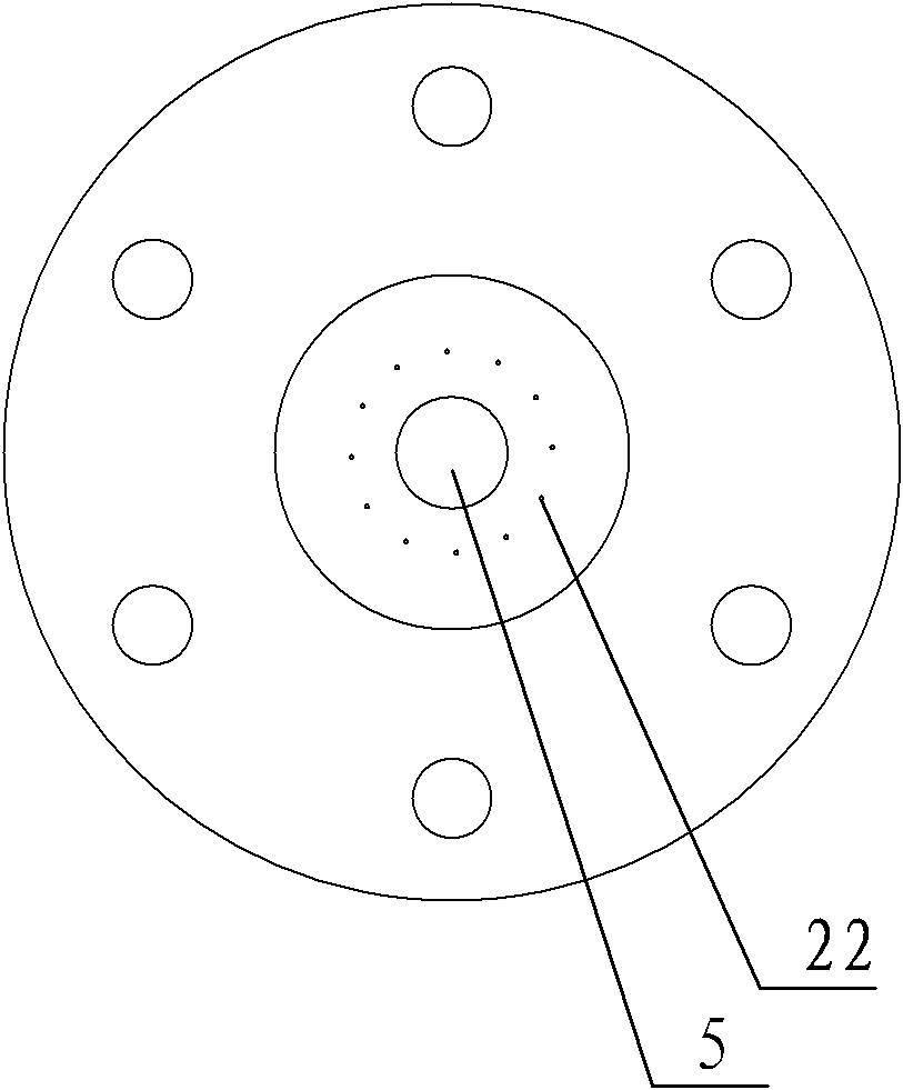
[0029] Such as figure 2 and image 3 As shown, the oxidant inlet pipe 1, the combustion agent inlet pipe 3, the gas-liquid dual-component nozzle 2, the injector panel 23 and the combustion agent chamber 4 form an injector, which includes an oxidant direct-flow nozzle 22, and three combustion agent nozzles. Self-strike direct-flow nozzle 21, twelve combustion agent direct-flow nozzles 5, and the circumference of combustion agen...


PUM


Abstract

The invention relates to a gas-liquid component high chamber-pressure large-range variable working condition combustor which comprises a spray injector, a spray pipe and an electric spark igniter, wherein the spray injector comprises an oxidizing agent inlet pipe, a combustion agent inlet pipe, a gas-liquid bi-component nozzle, a spray injector panel and a combustion agent cavity, the gas-liquid bi-component nozzle comprises a throttle hole, the spray injector panel, an oxidizing agent direct flow nozzle and three combustion agent self-striking direct flow nozzles, wherein the oxidizing agent direct flow nozzle is arranged in the middle part of the gas-liquid bi-component nozzle and is provided with an opening in the center of the spray injector panel; the three combustion agent self-striking direct flow nozzles are arranged on the side wall of the oxidizing agent direct flow nozzle; the throttle hole is arranged between the oxidizing agent inlet pipe and the oxidizing agent direct flow nozzle; the combustion agent cavity is a liquid cavity surrounding the external circumference of the oxidizing agent direct flow nozzle; and a plurality of combustion agent direct flow nozzles are arranged on the spray injector panel. The invention solves the technical problems of low chamber pressure, low thrust and insufficient small-range variable working condition capability of the traditional gas-liquid component combustor, and relatively high residual oxygen coefficient in the center and relatively low residual oxygen coefficient in a circumferential direct flow nozzle region are realized.

Description

technical field [0001] The invention relates to a burner. Background technique [0002] In the prior art, the combustor using the propellant as a gas-liquid component is supplied by propellant extrusion, so the ability to change working conditions is also weak. The extrusion method is not suitable for high chamber pressure, so it is necessary to study the burner with high chamber pressure and wide range of variable working conditions. Contents of the invention [0003] The purpose of the present invention is to provide a new gas-liquid component burner with high chamber pressure and wide range of variable working conditions, which solves the technical problems of the existing gas-liquid component burner with low chamber pressure, low thrust, and insufficient ability to change working conditions in a small range . [0004] Technical solution of the present invention is: [0005] A gas-liquid component high-chamber-pressure variable-range burner, including an injector, a ...

Claims


Application Information

Patent Timeline
IPC IPC(8): F23D17/00
Inventor 刘兴庆段增斌张金容韩俊峰杨小利李宝荣王魁丰雪平孙永奇
Owner NO 11 INST OF NO 6 ACADEMY OF CHINA AEROSPACE SCI & TECH
Learn More