
Boundary scan test method and device for reducing noise

A boundary scan test and noise technology, applied in the direction of measuring devices, measuring electricity, measuring electrical variables, etc., to achieve the effect of reducing noise, improving accuracy, and high fault coverage

Active Publication Date: 2011-01-26
BEIJING AEROSPACE MEASUREMENT & CONTROL TECH
View PDF5 Cites 6 Cited by
  • Summary
  • Abstract
  • Description
  • Claims
  • Application Information

AI Technical Summary

Problems solved by technology

[0006] The technical problem to be solved by the present invention is to provide a noise-reducing boundary-scan testing method and device, which can reduce the noise of the boundary-scan test signal and improve the accuracy of the test without increasing the complexity of the test.

Method used


Image

  • Boundary scan test method and device for reducing noise
  • Boundary scan test method and device for reducing noise
  • Boundary scan test method and device for reducing noise

Examples


no. 3 example

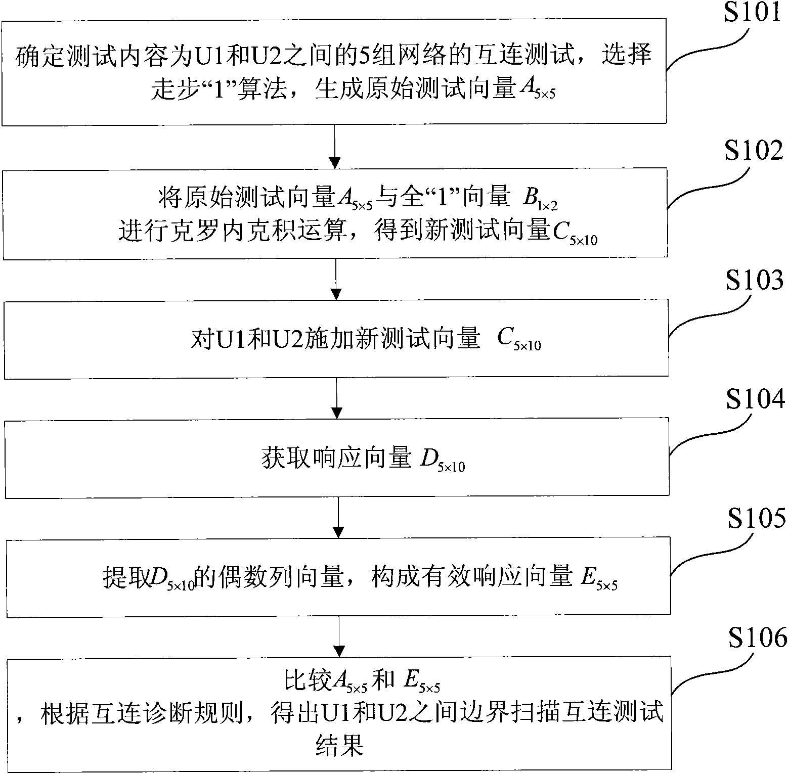
[0072] The third embodiment of the present invention, a boundary scan test method that can reduce noise, such as Figure 6 shown, including the following specific steps:

[0073] Step S301, generating an original test vector according to the boundary scan test content;

[0074] Step S302 , in the original test vector, add at least one parallel test vector identical to it immediately after each column of parallel test vectors to obtain a new test vector, and each column of parallel test vectors and the same parallel test vectors added subsequently form a parallel test vector group.

[0075] The process of obtaining a new test vector in this step can be realized by performing Kronecker product operation on the original test vector and all "1" vectors:

[0076] If a parallel test vector identical to the parallel test vector is added immediately after each column of parallel test vectors, the number of rows of all "1" vectors must be selected as 1, and the number of columns of al...

no. 4 example

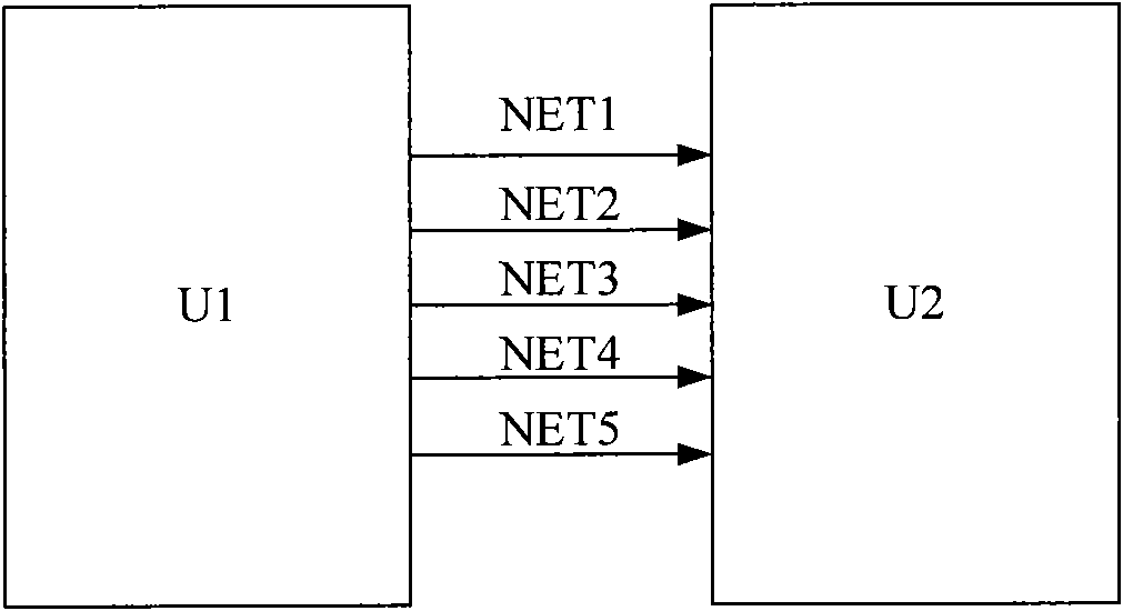
[0082] The fourth embodiment of the present invention corresponds to the third embodiment. This embodiment introduces a noise-reducing boundary-scan testing device, such as Figure 7 As shown, it includes the following components:

[0083] The original test vector generation module is used to generate the original test vector according to the boundary scan test content;

[0084] The new test vector generation module is used to add at least one parallel test vector identical to it next to each column of parallel test vectors in the original test vector to obtain a new test vector, and each column of parallel test vectors is composed of the same parallel test vectors added thereafter Parallel test vector group;

[0085] The test implementation module is used to impose a new test vector on the test object and obtain a response vector;

[0086] An effective response vector acquisition module is used to extract a vector that is not disturbed by noise as an effective response vect...


PUM


Abstract

The invention discloses a boundary scan test method and a boundary scan test device for reducing noise. The method comprises the following steps of: generating the original test vector according to test contents; processing the original test vector to acquire a new test vector; applying the new test vector to a tested object to acquire a response vector at the same time; extracting the response vector corresponding to the newly-added test vector; and performing diagnosis on the boundary scan test by using the extracted response vector as a final effective analysis vector. The device comprises an original test vector generation module, a new test vector generation module, a test implementation module, an effective response vector acquisition module and a diagnosis analysis module. The method and the device can effectively reduce the noise caused by the boundary scan test, improve the accuracy of the test, are simple to implement, do not need to add any test hardware and have high fault coverage rate.

Description

technical field [0001] The invention relates to the technical field of circuit testing, in particular to a noise-reducing boundary-scan testing method and device. Background technique [0002] As microelectronics technology enters the era of VLSI, the high complexity of circuits and the application of multilayer printed board, surface mount, wafer-scale integration and multi-chip module technologies in circuit systems make the physical reliability of circuit nodes Accessibility is gradually diminishing or even disappearing, the testability of circuits and systems is declining sharply, and the proportion of test costs in the total cost of circuits and systems is constantly rising. For the increasingly complex layout of circuit devices, complex packaging of components, dense pins; miniaturization of circuit boards, thinner and thinner lines, etc., these problems will bring a lot of problems to circuit line detection, circuit board fault inspection and troubleshooting. Big tro...

Claims


Application Information

Patent Timeline
IPC IPC(8): G01R31/3183
Inventor 徐鹏程杜影王石记安佰岳
Owner BEIJING AEROSPACE MEASUREMENT & CONTROL TECH
Learn More