
Detecting method of high order modulated MIMO system in mobile environment

A high-order modulation and detection method technology, applied in the field of communication, can solve the problems of high MSD detection complexity and high detection complexity

Inactive Publication Date: 2011-01-26
XIDIAN UNIV
View PDF2 Cites 11 Cited by
  • Summary
  • Abstract
  • Description
  • Claims
  • Application Information

AI Technical Summary

Problems solved by technology

However, in the case of high-order modulation, high-order MIMO and low SNR, the detection complexity of SD is still very high, which needs to be further reduced
In order to reduce the complexity of SD, a lot of research has been carried out at home and abroad from the perspective of reducing the number of search nodes and reducing the amount of calculation on each node. These algorithms obviously reduce the complexity of SD, but for Higher order modulation for higher communication rates and higher order MIMO systems challenge these low complexity methods
In order to reduce the problem of increased complexity of MIMO detection caused by high-order modulation and high-order MIMO, multi-state spherical detection MSD "Cui Tao, Tellambura C. Approximate ML Detection for MIMO Systems Using Multistage SphereDecoding [J] Signal Processing Letters, 2005, 12 (3): 222-225 "From the perspective of modulation layering, the high-order modulation constellation points are converted into a linear combination of multiple low-order modulation constellation points, and the SD detection process of high-order modulation is converted into multiple low-order modulations. SD detection process. Although this method reduces the detection complexity of the SD method under low SNR to a certain extent, the MSD detection complexity is still high under high SNR, high-order modulation and high-order MIMO.

Method used


Image

  • Detecting method of high order modulated MIMO system in mobile environment
  • Detecting method of high order modulated MIMO system in mobile environment
  • Detecting method of high order modulated MIMO system in mobile environment

Examples


Embodiment Construction

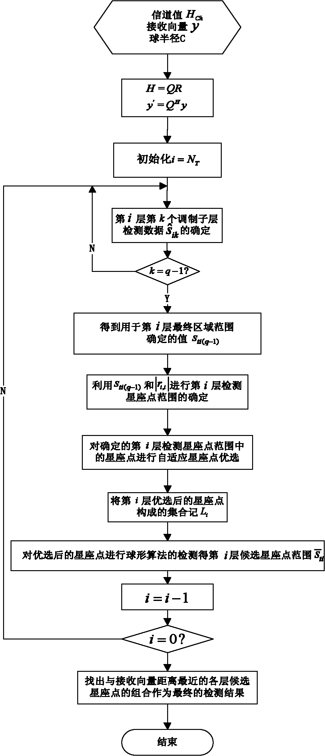
[0045] refer to figure 1 , the specific implementation steps of the present invention are as follows:

[0046] Step 1, data preparation, obtain the channel value H through the channel estimation method Ch , the spherical radius C of the present invention is obtained by spherical detection, and the receiving vector y is obtained directly from each receiving antenna.

[0047] Step 2, for the channel value H Ch , receive vector y for data processing, let H Ch =QR,y'=Q H In formula y, H Ch Represents the channel matrix, Q is the column orthogonal matrix, R is the upper triangular matrix, H represents the conjugate transpose, and y is the receiving vector.

[0048] Step 3, constructing data formulas for detecting each modulation sublayer of each layer.

[0049] (3a) According to the data received by the receiving antenna and the channel value, construct the detected transmitting antenna data formula:

[0050] s ^ = [ ...


PUM


Abstract

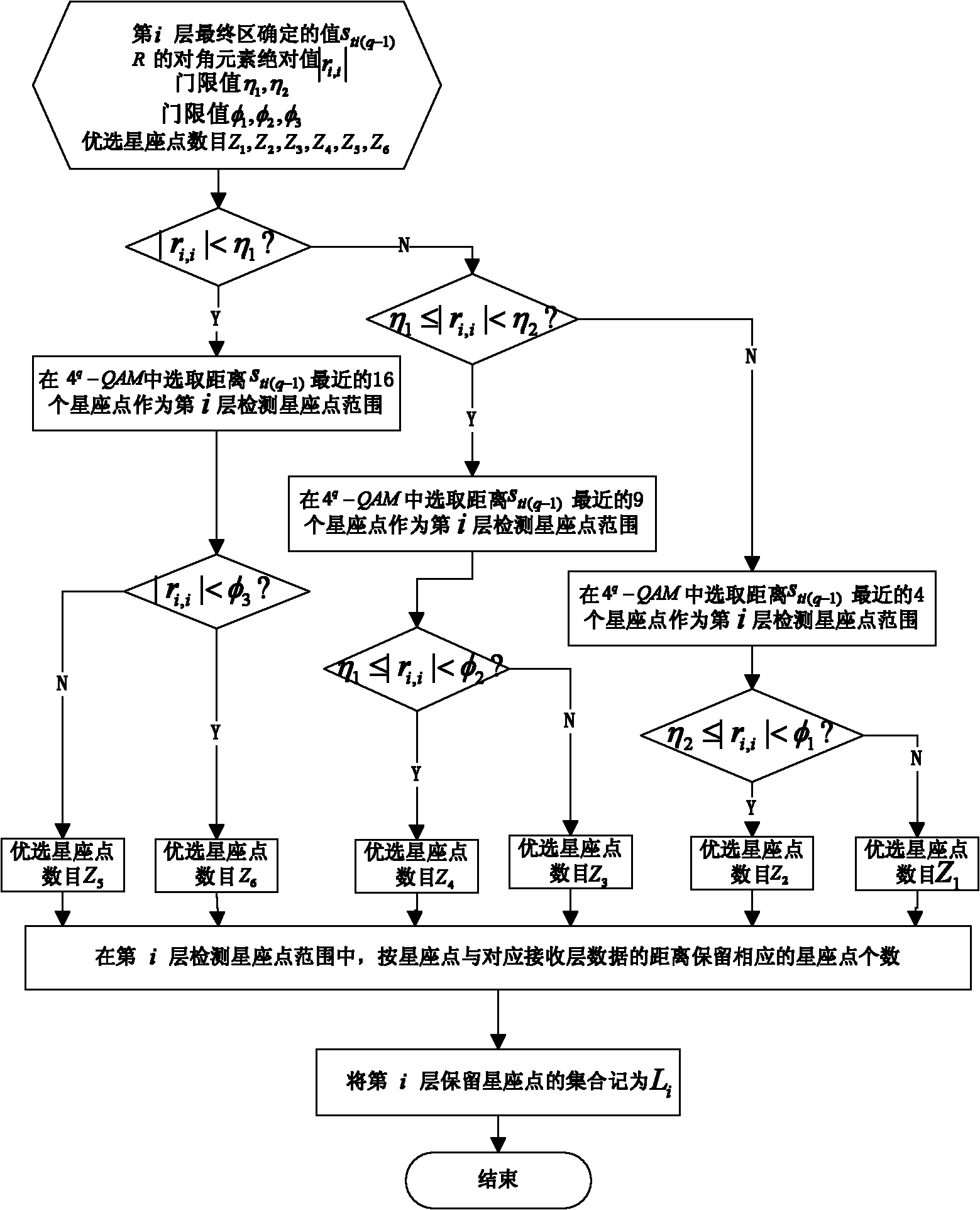
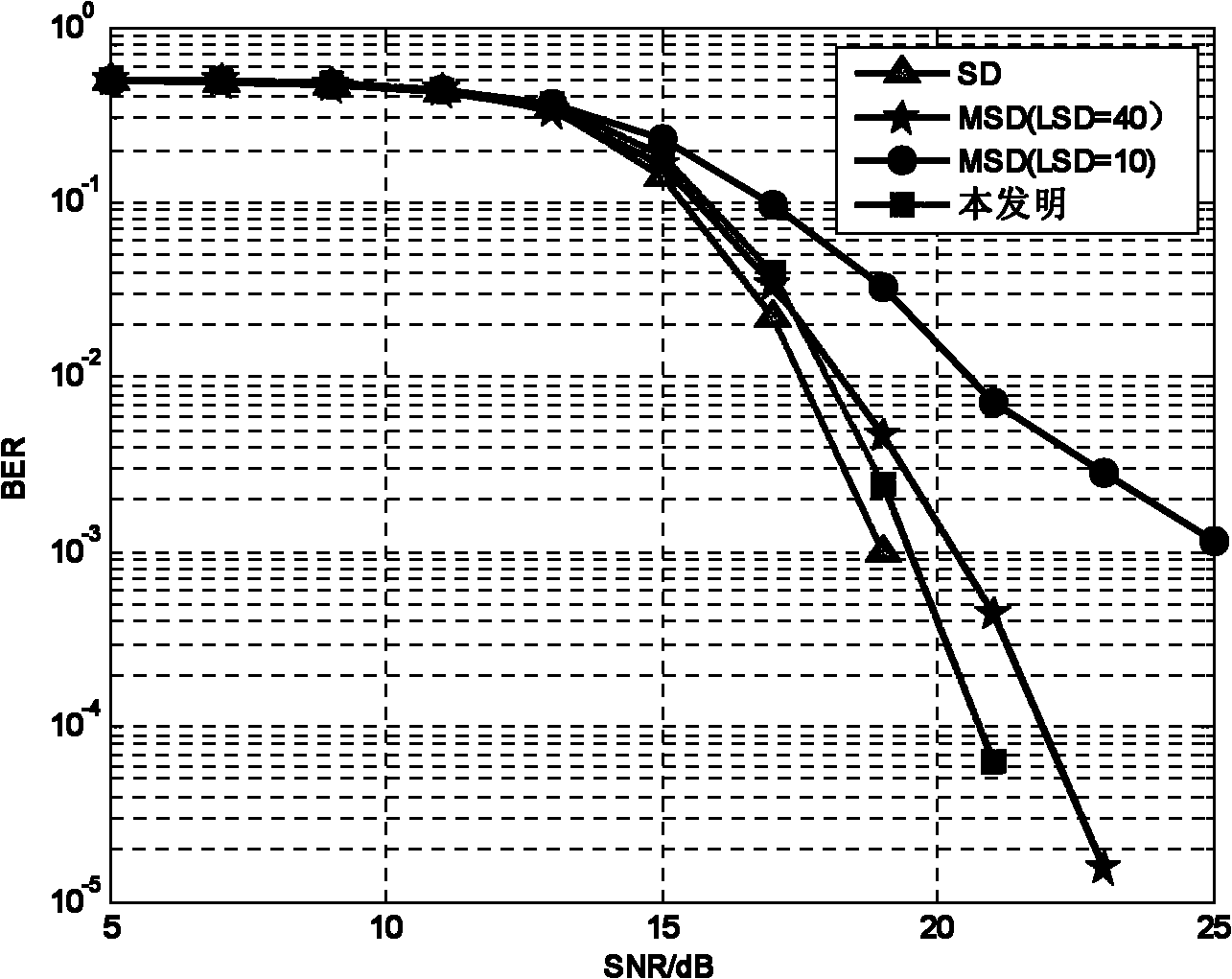
The invention provides a detecting method of high order modulated (multi-input multi-output) MIMO system in a mobile environment. The method mainly solves the problem that the current high order 4q-QAM modulated MIMO multiplex system has a high detection complexity. The detecting method comprises the following steps of: performing a region division for the constellation points of the 4q-QAM according to the stratified characteristic of the 4q-QAM; determining candidate regions based on the modulated sublayer data with greater weight coefficient; preferring the constellation points in the candidate regions according to a principle of minimum distance between the constellation points and corresponding received data; searching for preferred constellation points of each layer by using a spherical detection (SD) algorithm and determining transmitted data. Compared with a multi-state spherical detection (MSD) method, the detecting method has a lower complexity and a higher bit error rate performance; compared with the SD, the detecting method has a much lower complexity in a high signal to noise ratio (SNR) or a low SNR; therefore, the detecting method can be used in the design and realization of receiver in the high order modulated MIMO system in a mobile environment.

Description

technical field [0001] The invention belongs to the technical field of communication, and relates to the detection of a multiple-input multiple-output MIMO system, in particular to a method for reducing the complexity of MIMO detection, which can be used for detection of high-order MIMO based on high-order modulation. Background technique [0002] The spatial multiplexing MIMO system makes full use of space resources and effectively improves the frequency band utilization of the mobile communication system; with the further improvement of high-quality multimedia communication services on the system information transmission rate, under the condition of limited bandwidth, spatial multiplexing The MIMO system needs to adopt higher-order modulation methods such as 64QAM and higher-order MIMO to meet the system's requirements for transmission rates. Wireless communication physical layer standards have been formulated, such as ieee802.11n, ieee802.16e, and LTE, etc., and 64QAM has...

Claims


Application Information

Patent Timeline
IPC IPC(8): H04L27/36H04B7/06H04B17/00H04B17/20
Inventor 任光亮段昕利杨丽花张会宁
Owner XIDIAN UNIV
Learn More