
Electric box turnover device

A box-turning device and electric technology, which is applied in the direction of mold handling equipment, manufacturing tools, metal processing equipment, etc., can solve the problems of high labor intensity, unsafety, and low work efficiency, so as to reduce labor intensity and be safe and convenient to use , the effect of high flipping efficiency

Inactive Publication Date: 2011-02-02
JIANGSU HONGDE SPECIAL PARTS CO LTD
View PDF8 Cites 6 Cited by
  • Summary
  • Abstract
  • Description
  • Claims
  • Application Information

AI Technical Summary

Problems solved by technology

[0002] The practical large-scale sand box in the non-mechanized molding section of the foundry workshop often needs to lift the mold to the place where the sand is placed. After the sand is placed, it is necessary to turn over the box. Turn the sand box at a certain angle to spray the paint, and then lift and transport it. Turning over can complete the process of box closing and box opening. These tasks used to be done manually or with the assistance of ordinary crane spreaders. The labor intensity is high, the work efficiency is low, and it is not safe. The sand boxes and molds of some large castings have to be lifted and turned over. Continue to the next process of modeling, and some large castings need to be turned over for painting, cleaning and other processes, but the existing equipment does not have the ability to individually realize the electric suspension turning of the sand box

Method used


Image

  • Electric box turnover device
  • Electric box turnover device
  • Electric box turnover device

Examples


Embodiment Construction

[0014] specific implementation plan

[0015] An embodiment of an electric box-turning device with a lifting tonnage of 4 tons will now be further described in detail in comparison with the accompanying drawings.

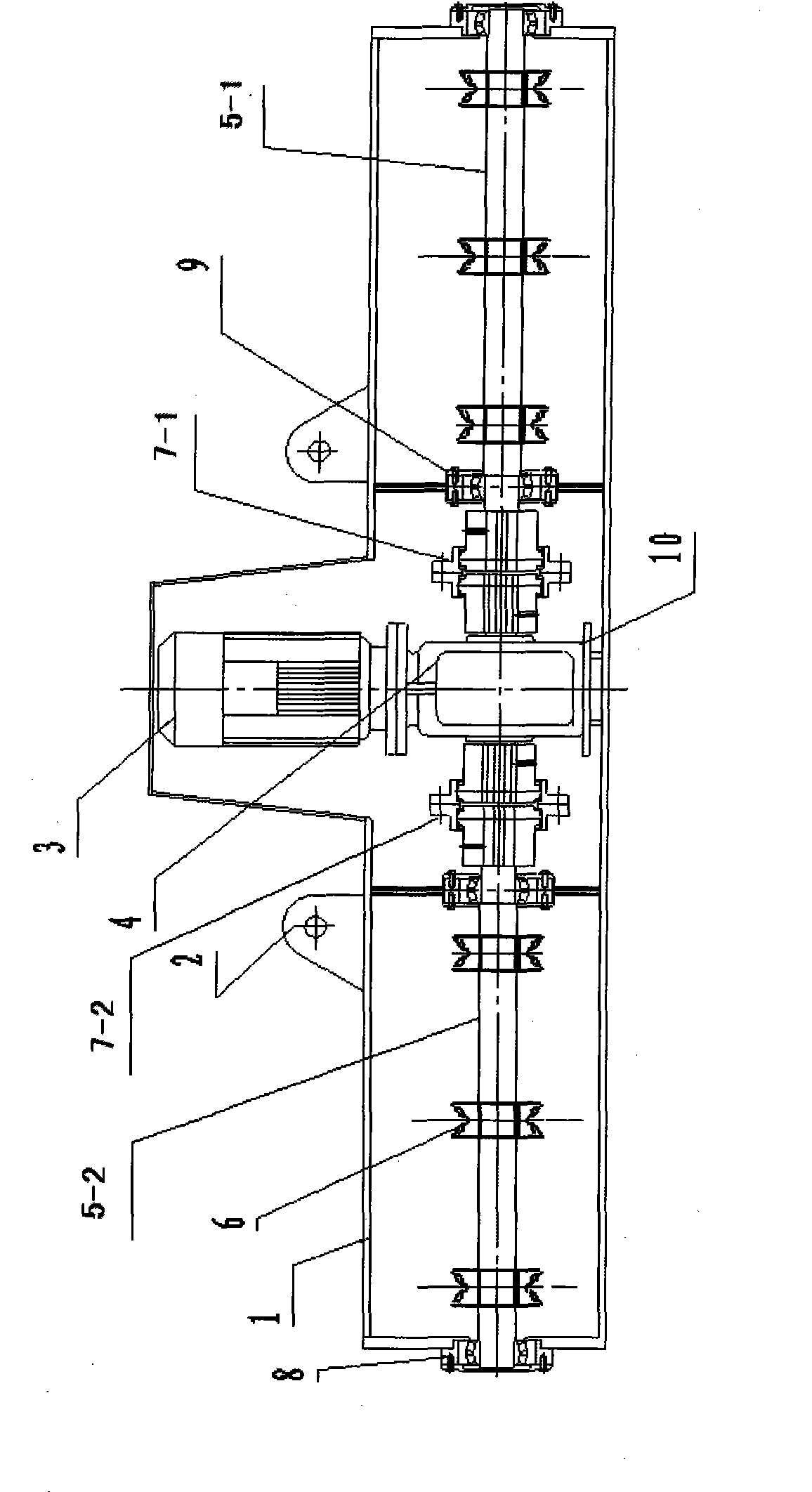
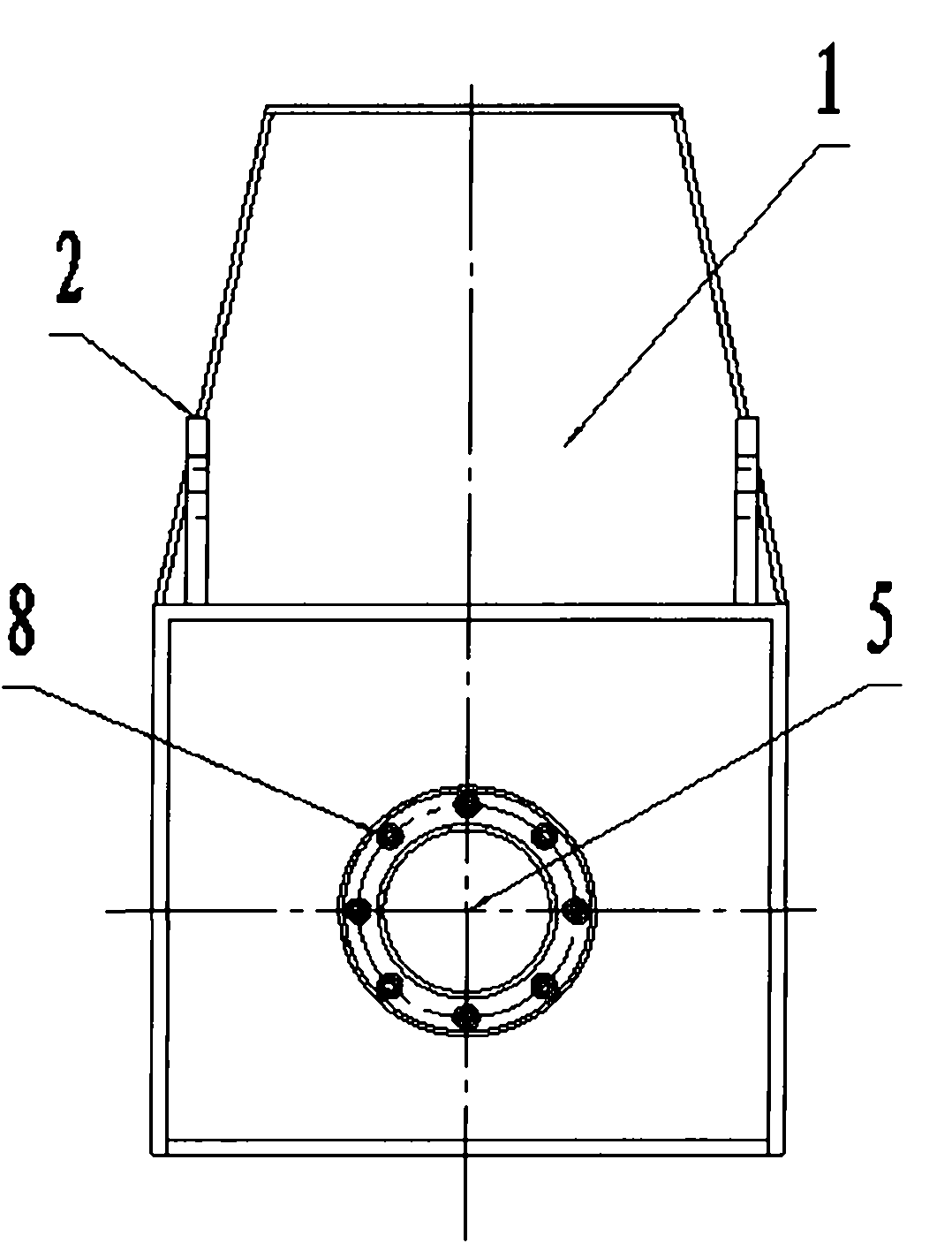
[0016] figure 1 It is a structural schematic diagram of the electric box turning device of the present invention, figure 2 It is the left view of the electric box turning device of the present invention. Such as figure 1 , 2 As shown, an electric box turning device includes a casing 1, a turning motor 3, a reducer 4, a transmission shaft, and a chain sprocket 6, wherein the casing 1 is welded by steel plates, and the front is in a convex shape. Four lifting lugs 2 are welded symmetrically on the four corners of the top of the body 1 that are mainly stressed, which is convenient for the lifting equipment to lift the whole device. The lower part of the shell 1 is open, and the groove on the top of the shell 1 is equipped with a Turnover motor 3, speed reducer 4 i...


PUM


Abstract

The invention relates to an electric box turnover device. Lifting lugs are symmetrically arranged on the top of an outer shell. The device is characterized in that: the shell has a convex framework with an opening; a bracket is arranged between front and back walls; a speed reducer is arranged on the bracket; a turnover motor is connected with the speed reducer and arranged above the speed reducer and in a groove of the shell; the two sides of the speed reducer are symmetrically connected with transmission shafts through couplings; the other end of each transmission shaft is supported on the side wall of the shell through a bearing; each transmission shaft is provided with a plurality of link chain sprockets; the transmission shafts and the link chain sprockets are fixed through keys and keyways; slots and slot grooves are formed on the link chain sprockets at equal intervals; and the widths of the slots and the slot grooves are respectively matched with the width and thickness of the link chain sprockets. The electric box turnover device can realize the controlled motion and stop 360-degree forward and reverse continuous or joggle electric turnover of a sand box, has low rotating speed and high turnover efficiency, stably operates and can be used for the turnover and close of the sand box, the inclined spraying of a flow coating sand box, the turnover of a casting mold and a tool and the turnover of large castings during processing.

Description

technical field [0001] The invention relates to an electric box turning device, which is an electric suspension turning machine used for sand box turning and moving. Background technique [0002] The practical large-scale sand box in the non-mechanized molding section of the foundry workshop often needs to lift the mold to the place where the sand is placed. After the sand is placed, it is necessary to turn over the box. Turn the sand box at a certain angle to spray the paint, and then lift and transport it. Turning over can complete the process of box closing and box opening. These tasks used to be done manually or with the assistance of ordinary crane spreaders. The labor intensity is high, the work efficiency is low, and it is not safe. The sand boxes and molds of some large castings have to be lifted and turned over. Continue to the next process of modeling, and some large castings need to be turned over for painting, cleaning and other processes, but the existing equipm...

Claims


Application Information

Patent Timeline
IPC IPC(8): B22D33/02B22D29/00
Inventor 杨金德朱懂飞
Owner JIANGSU HONGDE SPECIAL PARTS CO LTD
Learn More