Oil tank level transmitting device

An oil storage tank, liquid level technology, applied in the direction of the liquid level indicator for the measurement of physical variables, etc., can solve the problems of difficulty in ensuring stability and reliability, the sensitivity of the liquid level sensor is discounted, and the measurement accuracy cannot be guaranteed. Good elastic deformation, easy repair and maintenance, high pressure sensitivity effect

Inactive Publication Date: 2011-02-09
HEFEI INSTITUTES OF PHYSICAL SCIENCE - CHINESE ACAD OF SCI
View PDF3 Cites 5 Cited by
  • Summary
  • Abstract
  • Description
  • Claims
  • Application Information

AI Technical Summary

Problems solved by technology

However, there are deficiencies in the liquid level sensor in this environmental state measuring instrument. First, a pair of detection electrodes must directly contact the liquid level at the same time, and the liquid to be measured must be thin and easy to flow, while the crude oil in the oil storage tank must be thin and easy to flow. However, it is a viscous medium, and the maximum static pressure can reach 0.6Mpa, which not only greatly reduces the sensitivity of the liquid level sensor, but also cannot guarantee the accuracy of its measurement; secondly, the working temperature in the oil storage tank is as high as 80°C or above , crude oil is a corrosive medium, which makes it difficult to guarantee the long-term stability and reliability of the detection electrodes used in cylindrical metal covered with metal film structures; again, a pair of detection electrodes placed in the casing is passed The through hole at the bottom of the casing is in contact with the medium in the liquid storage tank. When it is placed in the oil in the oil storage tank, the through hole is easily blocked by viscous oil, making it impossible to measure accurate oil. liquid level, and it is not easy to carry out daily repair and maintenance

Method used


Image

  • Oil tank level transmitting device
  • Oil tank level transmitting device
  • Oil tank level transmitting device

Examples


Embodiment Construction

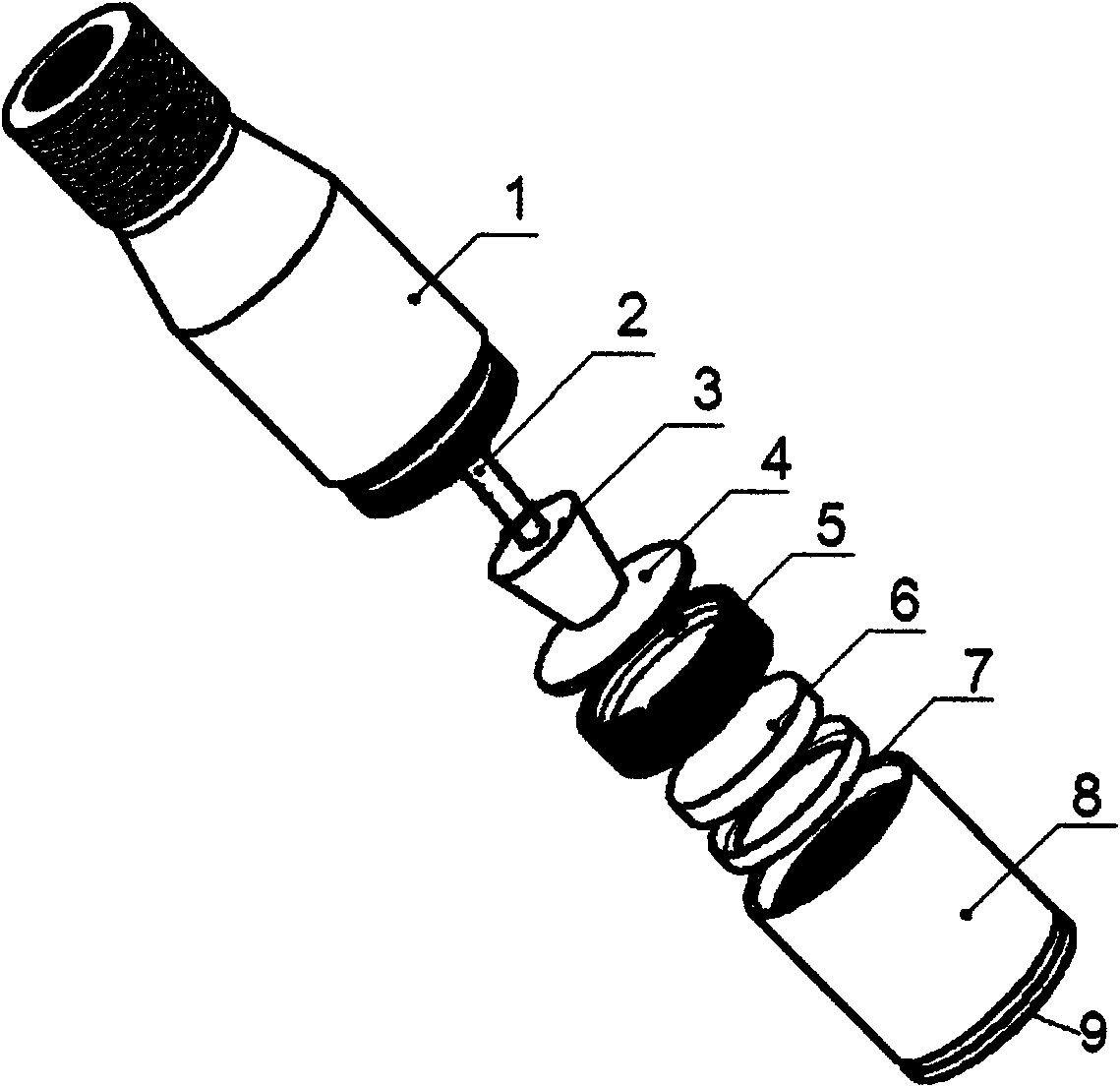
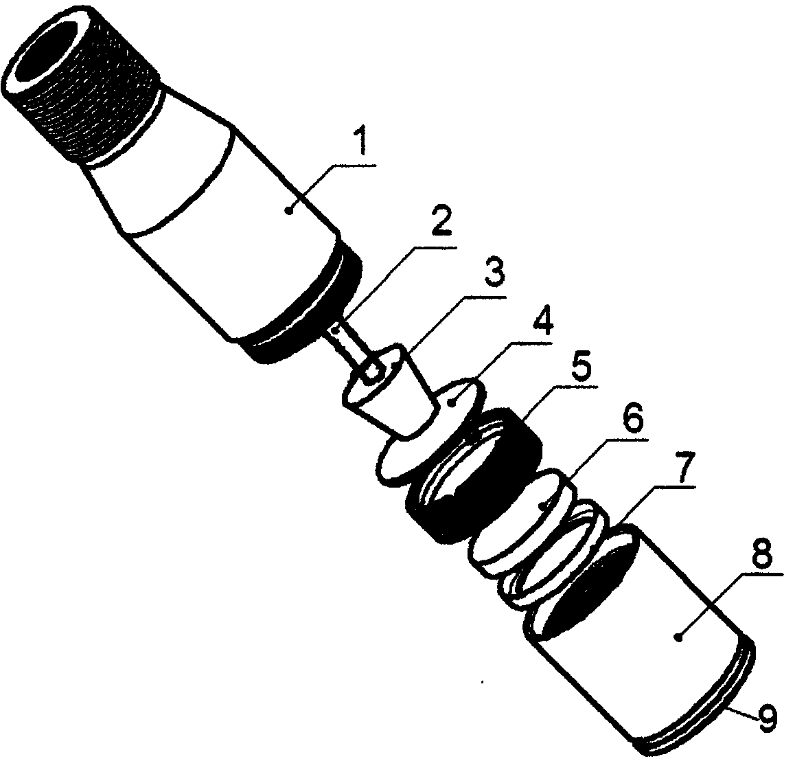
[0015] see figure 1 and figure 2 , the cylindrical sealing sleeve is composed of an upper cover 1 and a base 8, wherein the upper cover 1 and the base 8 are fixedly connected through threads (or buckles), the port of the base 8 is provided with a window 9, and the window 9 is provided with a sensor part.

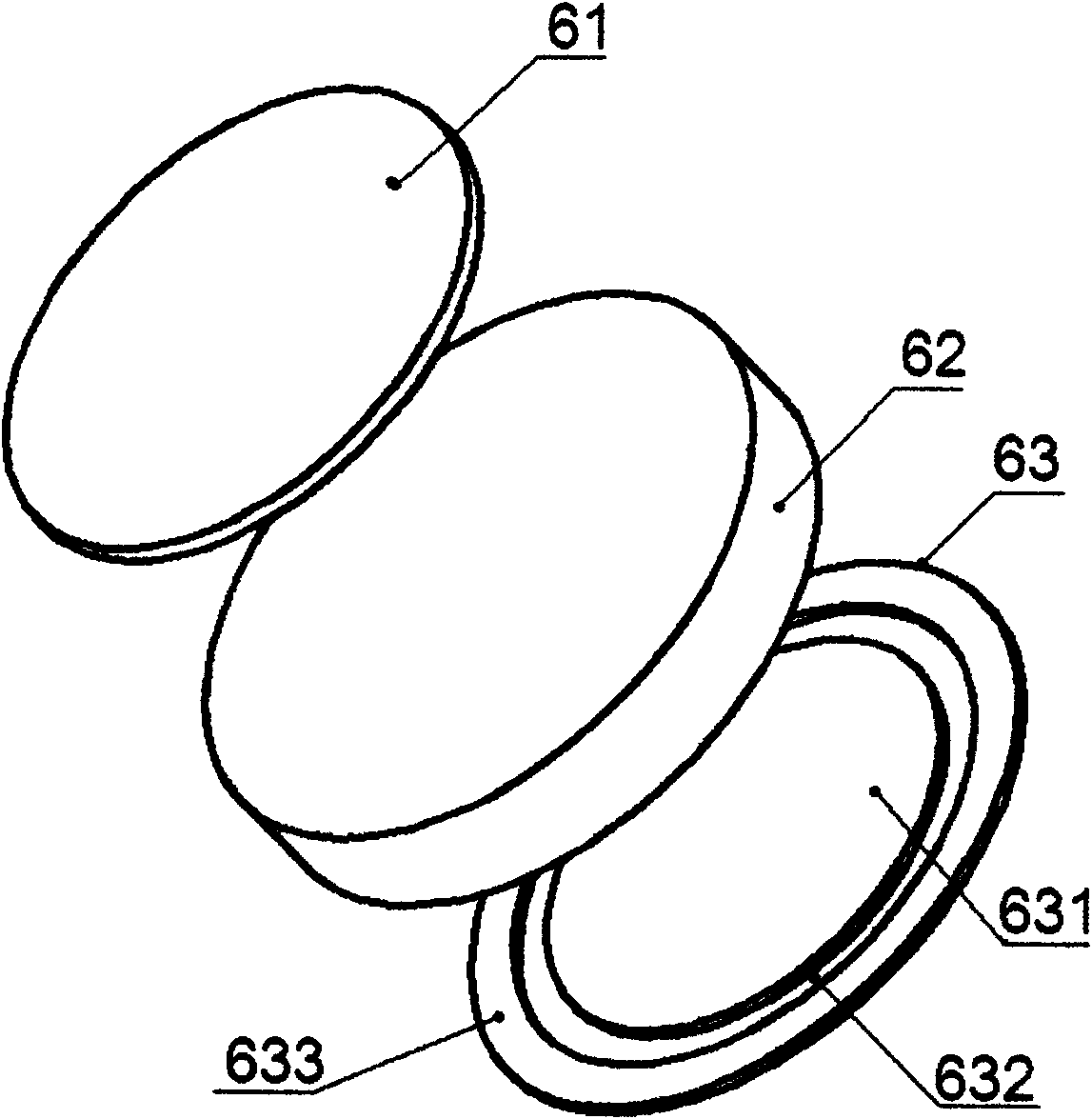
[0016] The sensing component is a capacitive pressure sensing component 6, which is composed of an electrically connected capacity voltage converter 61, a flat capacitor upper plate 62 and a flat capacitor lower plate 63; wherein, the capacitor upper plate 62 is Thickness is the ceramic plate of 55mm (can be selected between 50~60mm), and the lower electrode plate 63 of the capacitor is a common electrode, and it is 0.6mm (can be selected between 0.5~0.65mm) with the thickness of composite layer on one side. Composed of ceramic plates, wherein the ceramic plates as the upper plate 62 of the capacitor and the lower plate 63 of the capacitor are all aluminum oxide (AL 2 o ...


PUM


Abstract

The invention discloses an oil tank level transmitting device comprising a sensing part and a signal transmitting part which are electrically connected in a sleeve tube, wherein the sleeve tube is a sealing sleeve tube formed by an upper cover (1) and a base (8); the end part of the base (8) is provided with a window (9) on which the sensing part is arranged; the sensing part is a capacitance type pressure sensing part (6) formed by a capacity voltage converter (61), and a tabulate capacitance upper polar plate (62) and a tabulate capacitance lower polar plate (63); the output end of the capacity voltage converter (61) is electrically connected with the signal transmitting part through a sealing adapter plate (4); the sealing adapter plate (4) is positioned between the capacitance type pressure sensing part (6) and the signal transmitting part, and is provided with electric welding points penetrating through the plate body of the sealing adapter plate (4) and a waterproof molecule plug; and the signal transmitting part is a cable (2) axially and hermetically sheathed with a conducting wire and an air duct. The invention can be used for accurately measuring the oil level in the non-pressure oil tank and can be widely applied to oilfield production.

Description

technical field [0001] The invention relates to a liquid level transmission device, in particular to a liquid level transmission device for an oil storage tank. Background technique [0002] At present, in the process of oil collection, most oilfield enterprises temporarily store the oil sprayed or sucked out of the oil well in the oil storage tank next to the well. The oil liquid level in these numerous oil storage tanks distributed in the field It is an important parameter in oil production. Accurate monitoring of liquid level is of great significance to the automation and safety of oil field production process. There are many kinds of existing liquid level monitoring equipment, such as an "environmental state measuring instrument" disclosed in US 2008 / 0092647A1 published on April 24, 2008. The environmental state measuring instrument is intended to monitor the liquid level in the liquid tank in a timely manner. It is composed of an electrically connected liquid level sen...

Claims


Application Information

Patent Timeline
Patent Type & Authority Applications(China)
IPC IPC(8): G01F23/26
Inventor 常慧敏梅涛周平刘春艳王英先高理升马以武徐智晴
Owner HEFEI INSTITUTES OF PHYSICAL SCIENCE - CHINESE ACAD OF SCI
Why Eureka
Try Eureka