Fiber photoelastic effect based larger-area sound monitoring system

A monitoring system and large-area technology, which is applied in the direction of optical fiber transmission, transmission system, electromagnetic wave transmission system, etc., can solve the problems of background light variability, light shading, video technology limitations, and easy electromagnetic interference, etc., to achieve a large effective range , high sensitivity, high sensitivity effect

Active Publication Date: 2011-02-09
FUDAN UNIV
View PDF6 Cites 16 Cited by
  • Summary
  • Abstract
  • Description
  • Claims
  • Application Information

AI Technical Summary

Problems solved by technology

[0003] However, in the application of image and video monitoring tools represented by cameras, there are also some shortcomings: the variability of background light and the occlusion of light have greatly restricted video technology. In order to reduce observation blind spots, More cameras have to be added; the camera is an electronic device that needs power supply energy and is easily disturbed by electromagnetic interference, and can also be detected by electromagnetic anti-detection tools

Method used


Image

  • Fiber photoelastic effect based larger-area sound monitoring system
  • Fiber photoelastic effect based larger-area sound monitoring system
  • Fiber photoelastic effect based larger-area sound monitoring system

Examples


Embodiment 1

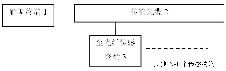
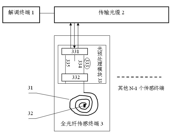
[0034] This embodiment is an example of performing phase modulation on an optical signal. combine figure 2 and Figure 4 , this embodiment includes a demodulation terminal 1, a transmission optical cable 2, and an all-fiber sensing terminal 3. Both ends of the transmission optical cable 2 are respectively connected to the demodulation terminal 1 and the all-fiber sensing terminal 3 . All-fiber sensing terminal 3 such as Figure 4 , which includes a sensing fiber 31, a reflector 32, and an optical preprocessing module 33; the optical preprocessing module 33 includes a 3 × 3 optical fiber coupler 331, a 2 × 2 optical fiber coupler 332, an optical fiber delay line 333, and an optical fiber jumper 334 . Fiber jumper 335, wherein the fiber jumpers 334, 335 are connected to the 3×3 fiber coupler 331 and the 2×2 fiber coupler 332, and the fiber delay line 333 is fabricated on the fiber jumper 334.

[0035] When applying the present invention, the demodulation terminal 1 is place...

Embodiment 2

[0048] This embodiment is an example of performing wavelength modulation on an optical signal. Such as Figure 5 As shown, this embodiment includes a demodulation terminal 1 , a transmission optical cable 2 , and an all-fiber sensing terminal 3 . Both ends of the transmission optical cable 2 are respectively connected to the demodulation terminal 1 and the all-fiber sensing terminal 3 . The all-fiber sensing terminal 3 is mainly composed of a sensing fiber 31 and a fiber grating 311 , and the fiber grating 311 is fabricated on the sensing fiber 31 .

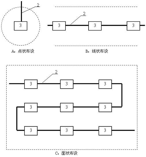
[0049] When applying the present invention, the demodulation terminal 1 is placed in a remote monitoring center, one end of the transmission optical cable 2 is connected to the demodulation terminal 1, and the other end is extended to the area to be tested, and distributed according to the specific conditions of the area to be tested. At the place where sound monitoring is required, the transmission optical cable 2 is stripped,...


PUM


Abstract

The invention belongs to the technical field of safety monitoring, in particular to a fiber photoelastic effect based larger-area sound monitoring system. The system comprises a remote demodulation terminal, full fiber sensing terminals in an area to be monitored and a transmission optical cable for connecting the demodulation terminal with the full fiber sensing terminals, wherein a large quantity of full fiber sensing terminals can be multiplexed on the transmission optical cable. In the invention, sensing fibers in the full fiber sensing terminals are used for extracting various sound signals in surrounding environment, and the transmission optical cable is utilized to acquire the information and returning the information to the demodulation terminal; and through corresponding analysis and processing, the information is really restored to realize the real-time monitoring of various sound signals in a large-range area to be monitored. The system mainly comprises passive fiber devices without comprising any electronic components, has no radiant electromagnetic waves, cannot be influenced by electromagnetic interference and is suitable for the fields of military affairs, public security, security, safety production, disaster prevention and control, and the like.

Description

technical field [0001] The invention belongs to the technical field of safety monitoring, and in particular relates to a passive, concealed, anti-detection and high-sensitivity large-area sound monitoring system. It can be used in military, public security, security, production safety, disaster prevention and control and other fields. Background technique [0002] For a long time, as a widely used video monitoring tool, the camera has been widely used in military, public security, security, production safety, disaster prevention and control and other fields, and achieved good results. In particular, it has played an important role in the recent construction of the "Skynet" project, providing an important means for the security of the city. [0003] However, in the application of image and video monitoring tools represented by cameras, there are also some shortcomings: the variability of background light and the occlusion of light have greatly restricted video technology. In...

Claims


Application Information

Patent Timeline
Patent Type & Authority Applications(China)
IPC IPC(8): H04B10/12H04B10/08H04B10/25
Inventor 贾波赵栋唐璜
Owner FUDAN UNIV
Why Eureka
Try Eureka