
Single tube type vacuum radiating system

A radiator and vacuum technology, applied in the direction of indirect heat exchangers, tubular elements, heat exchange equipment, etc., can solve the problems of high product cost, increased coal consumption, large heat loss, etc., to increase the heat dissipation effect, increase the Heating area and the effect of improving thermal efficiency

Inactive Publication Date: 2012-08-08
胡国强
View PDF0 Cites 0 Cited by
  • Summary
  • Abstract
  • Description
  • Claims
  • Application Information

AI Technical Summary

Problems solved by technology

[0002] At present, the conventional heating is mainly centralized heating and individual heating of residential units, resulting in increased coal consumption and huge investment in laying pipeline networks
The heat loss is large, the heating effect of the pipe is not ideal, the parts are budgeted for replacement and maintenance, and the product cost is high. The price of heating per square meter in winter is rising step by step. The burning of coal for heating pollutes the environment, the water consumption is large, and the process loss is also very large. And there are many security risks
[0003] As we all know, most of the hot water in the existing heating system uses coal, oil, and gas to burn boilers, which heat up the water and consume a large amount of non-renewable fuels.
In the existing heating system, the heat exchange rate is low, the boiler room needs a large area, the investment is large, the hot water pipeline is long and complicated, and the radiator is bulky

Method used


Image

  • Single tube type vacuum radiating system
  • Single tube type vacuum radiating system
  • Single tube type vacuum radiating system

Examples


Embodiment Construction

[0021] The present invention will be described in further detail below in conjunction with the accompanying drawings.

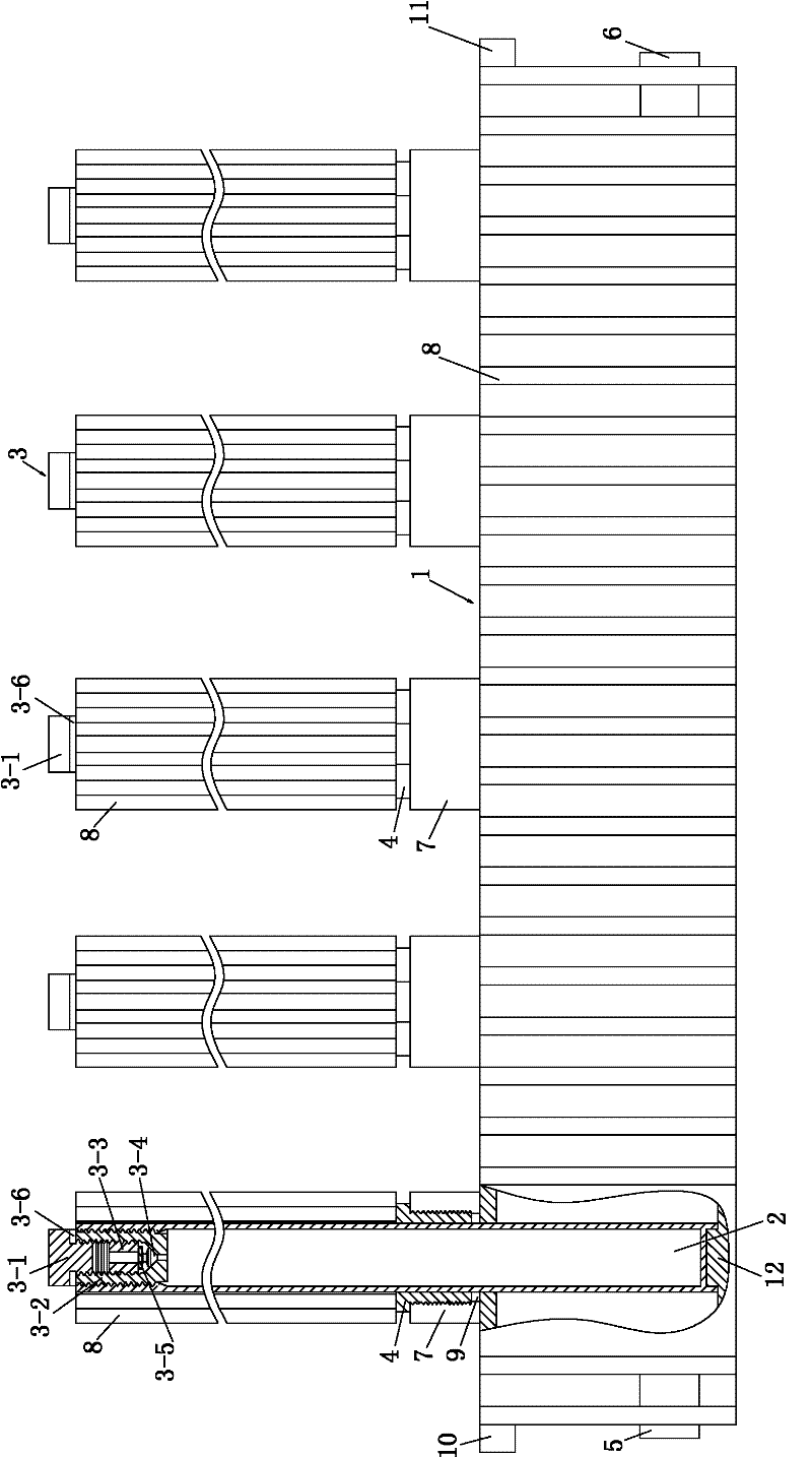
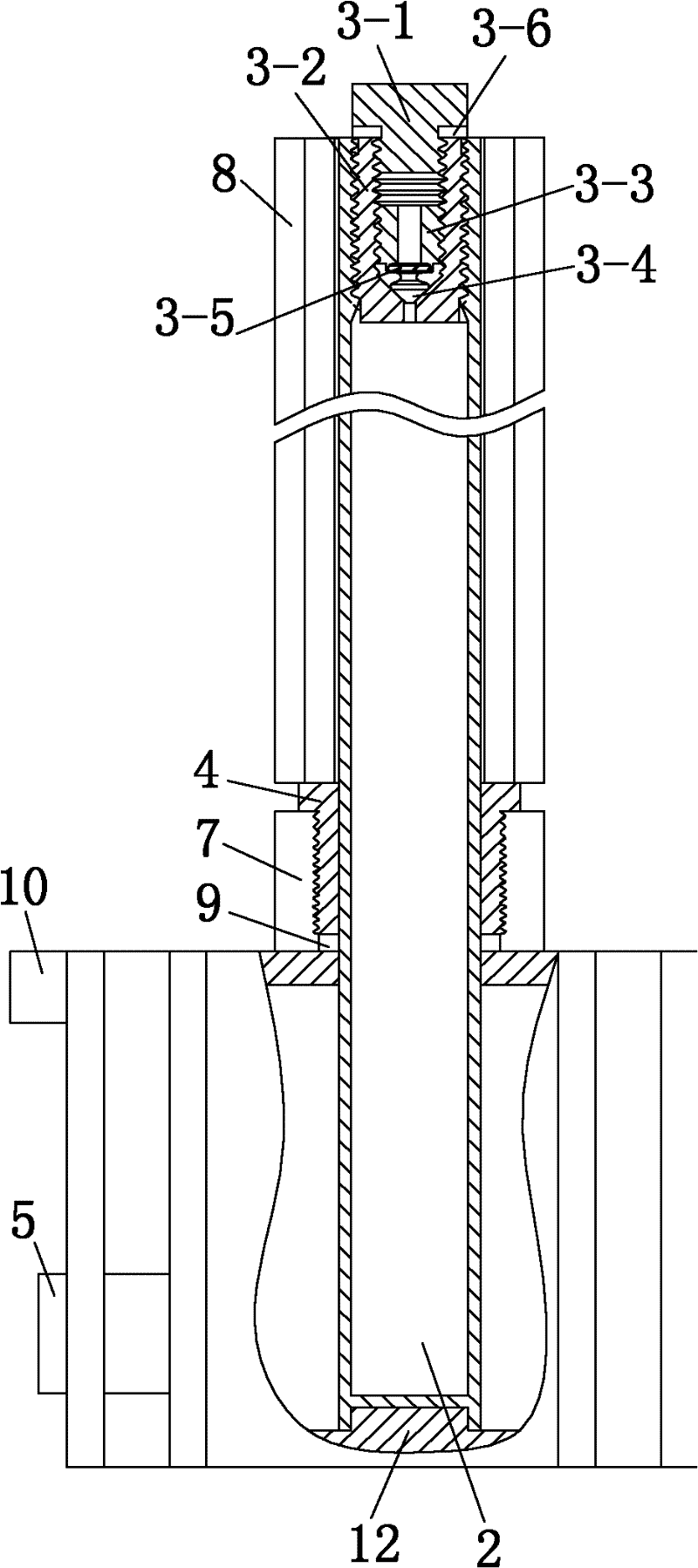
[0022] Such as Figure 1 to Figure 6 As shown, the single-pipe vacuum radiator of the present invention includes a water tank 1, a cooling pipe 2, a vacuum valve 3 and a hollow outer hex nut 4. The shape of the water tank 1 is roughly a rectangular parallelepiped water tank, made of cast iron material, and its exterior is welded with aluminum Special-shaped heat sink 8; one end of the water tank 1 is provided with a water inlet 5, and the other end is provided with a water outlet 6; the top of the water tank 1 is welded with a plurality of cooling pipe sockets 7, and the bottom is correspondingly cast with a plurality of fixing seats 12; the hollow outer hexagon The nut 4 is located in the radiating pipe socket 7, and is connected with the radiating pipe socket 7 by threads; The phase change medium can be acetone or ethylene glycol or a mixture of the two, f...


PUM


Abstract

A single tube type vacuum radiating device belongs to the technical field of radiating device. The device comprises a water tank, a radiating tube, a vacuum valve and a hollow outer hexnut, wherein one end of the water tank is provided with a water inlet while the other end is provided with a water outlet; the bottom of the water tank is provided with a fixed base and the top thereof is provided with a radiating tube faucet; the hollow outer hexnut is arranged in the radiating tube faucet and is threaded to the radiating tube faucet; the radiating tube is vacuumized and is fed with phase-change medium; the upper part of the radiating tube is sleeved with an aluminum abnormal-shaped radiating fin; the enclosed end of the radiating tube is inserted in the bottom of the water tank by passing through the hollow outer hexnut and is sleeved on the fixed base; and the vacuum valve is provided with outer screw thread and is in argon arc welding connection with the opening end of the radiating tube through an enclosed cover. In the single tube type vacuum radiating device of the invention, the heated area of the radiating tube is increased by using the water tank structure so as to achieve the maximum heat power radiated from the radiating tube, the metal materials of the radiating tube ensure that the device is free from leakage in structure, each radiating tube can be conveniently exchanged and the device can fully radiate.

Description

technical field [0001] The invention belongs to the technical field of heat dissipation systems, and relates to a single-pipe vacuum radiator. Background technique [0002] At present, the conventional heating is mainly centralized heating and individual heating of residential units, resulting in increased coal consumption and huge investment in laying pipeline networks. The heat loss is large, the heating effect of the pipe is not ideal, the parts are budgeted for replacement and maintenance, and the product cost is high. The price of heating per square meter in winter is rising step by step. The burning of coal for heating pollutes the environment, the water consumption is large, and the process loss is also very large. And there are many security risks. [0003] As we all know, most of the hot water in the existing heating system uses coal, oil, and gas to burn boilers to heat up the water and consume a large amount of non-renewable fuels. In the existing heating system...

Claims


Application Information

Patent Timeline
Patent Type & Authority Patents(China)
IPC IPC(8): F28D15/00F28D15/02F16K1/00F28F1/12
Inventor 胡国强
Owner 胡国强
Learn More