Method for measuring position and speed of rotor of electrically excited synchronous motor and control device

A technology of synchronous motor and rotor position, which is applied to devices using electric/magnetic methods, single motor speed/torque control, and wound-type excitation motor control. It can solve the problems of complex hardware structure of the speed closed-loop control system. Achieve the effects of improving reliability and speed control accuracy, simplifying system structure, and improving accuracy

Inactive Publication Date: 2011-02-16
CHINA UNIV OF MINING & TECH +1
View PDF5 Cites 7 Cited by
  • Summary
  • Abstract
  • Description
  • Claims
  • Application Information

AI Technical Summary

Problems solved by technology

[0005] The purpose of the present invention is to provide a method and control device for measuring the rotor position and speed of an electric excitation synchronous motor, which solves the problem of complex hardware structure of the closed-loop control system of the synchronous motor speed, and at the same time improves the reliability and accuracy of the control system

Method used


Image

  • Method for measuring position and speed of rotor of electrically excited synchronous motor and control device
  • Method for measuring position and speed of rotor of electrically excited synchronous motor and control device
  • Method for measuring position and speed of rotor of electrically excited synchronous motor and control device

Examples


Embodiment 1

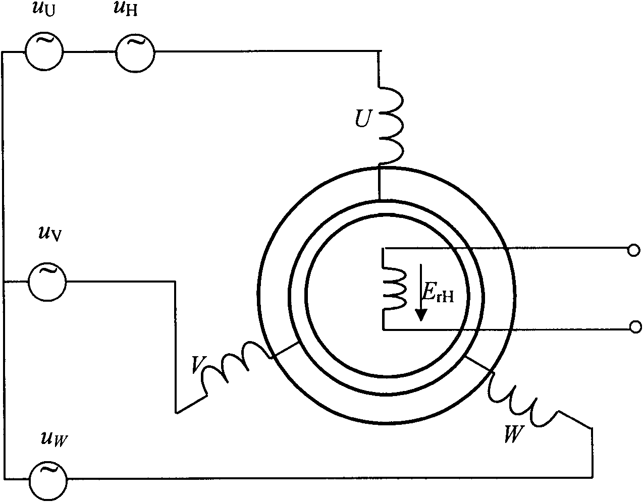
[0021] Embodiment 1: The measurement method for measuring the rotor position and speed of an electrically excited synchronous motor is:

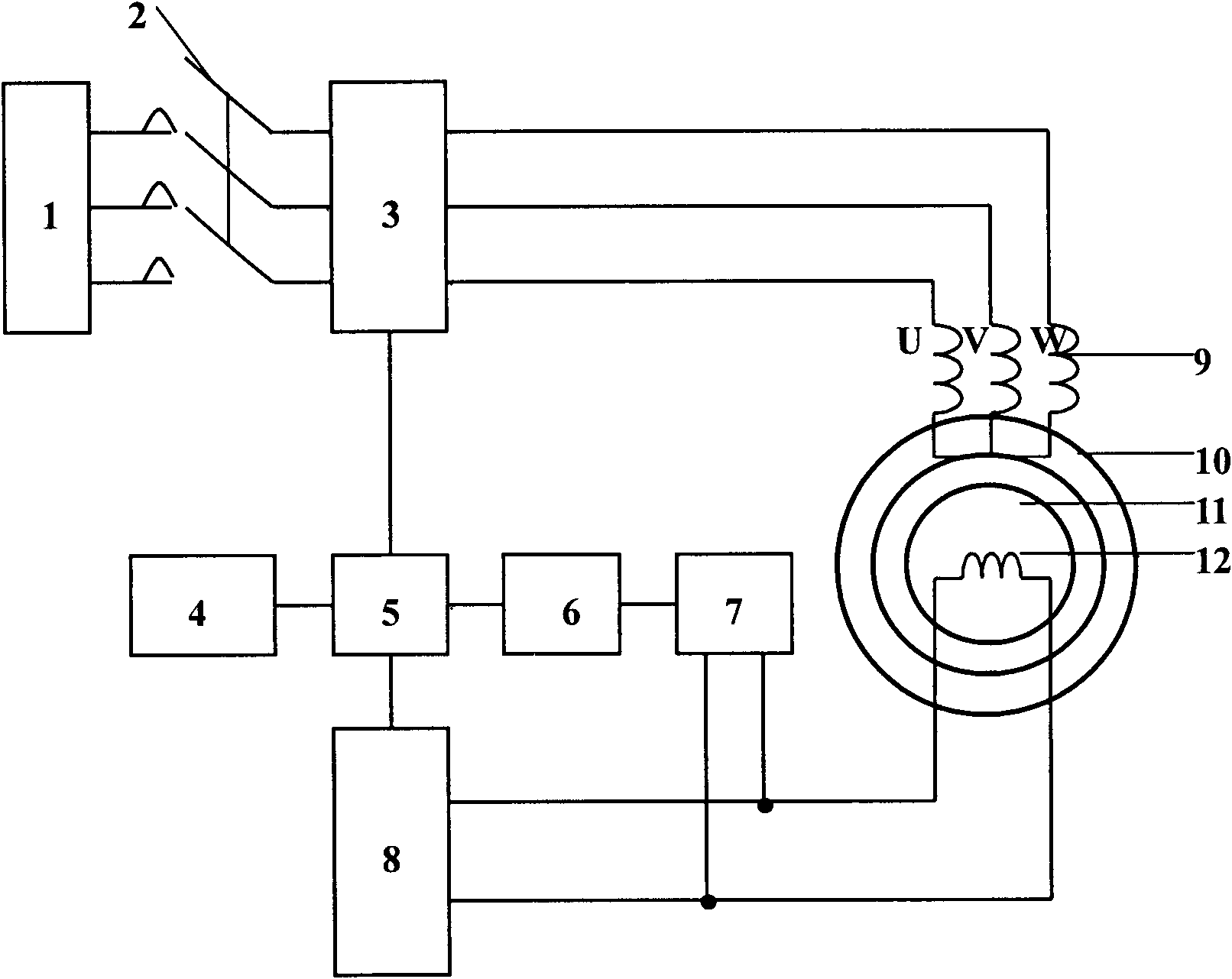
[0022] a. The system controller 5 controls the stator power converter 3. On the one hand, the stator power converter 3 outputs a three-phase AC voltage to supply power to the stator winding 9 of the synchronous motor; H high-frequency voltage signal;

[0023] b. The injection frequency is f in the phase U of the stator winding of the synchronous motor H The high-frequency excitation signal, the frequency induced from the synchronous motor rotor excitation winding 12 and the cosine relationship with the rotor angle θ is f H high-frequency potential signal;

[0024] c, the signal filter 6 extracts the frequency detected by the voltage transformer 7 as f H The high-frequency potential signal of the system controller 5 calculates the rotor position angle of the synchronous motor, and uses the derivative of the rotor angle θ to time to calcula...


PUM


Abstract

The invention discloses a method for measuring position and speed of a rotor of an electrically excited synchronous motor and a control device, and belongs to the measurement method and a control device for the synchronous motor. The method comprises the following steps of: injecting a high-frequency voltage signal at the U phase of a stator of the electrically excited synchronous motor; generating a high-frequency pulsating magnetic field by the high-frequency voltage signal, wherein a high-frequency potential signal induced in a rotor winding by the high-frequency pulsating magnetic field also changes along with position change of the motor rotor; acquiring the signal by a voltage transformer and determining the position of the rotor and the rotation speed of a synchronizer; feeding the measured rotor position signal and rotation speed signal back to a controller; and accurately controlling the speed of the electrically excited synchronous motor by the controller according to a given signal. The method and the device have the advantages that: the device is not provided with a mechanical speed sensor; by using the electromagnetic structure of the synchronous motor, the rotation speed of the motor is directly measured by injecting the high-frequency signal at one phase of the stator; and the composition of the system is simplified, and the reliability of the system and the accuracy for the speed control are improved.

Description

technical field [0001] The invention relates to a measuring method and a control device of a synchronous motor, in particular to a measuring method and a control device of a rotor position and speed of an electrically excited synchronous motor. Background technique [0002] In the high-performance synchronous motor vector control system, the closed-loop control link of rotor position and speed is essential. The speed sensor-based control system uses mechanical speed sensors such as photoelectric encoders and tachometer generators to detect the motor speed and feed back the speed signal. These systems have poor rotor position detection capabilities, mechanical speed sensors have installation problems, and increase the maintenance workload of the system. [0003] The current speed sensorless control system uses the detection of physical quantities such as motor stator voltage and current, and combines the asymmetry of the rotor magnetic circuit to estimate the position and sp...

Claims


Application Information

Patent Timeline
Patent Type & Authority Applications(China)
IPC IPC(8): H02P6/06G01P3/44H02P6/08H02P6/16H02P6/32
Inventor 邓先明谭国俊何凤有张晓王磊
Owner CHINA UNIV OF MINING & TECH
Why Eureka
Try Eureka