Supercharge Your Innovation With Domain-Expert AI Agents!

Plate type reactor, manufacturing method therefor, and reaction product manufacturing method using the plate type reactor

A technology for plate reactors and reaction products, which is applied in chemical instruments and methods, preparation of organic compounds, preparation of oxygenated compounds by oxidation of hydrocarbons, etc., and can solve the problems of reduced yield of target reaction products, pressure rise, and large pressure loss, etc.

Inactive Publication Date: 2011-02-16
MITSUBISHI CHEM CORP
View PDF14 Cites 4 Cited by
  • Summary
  • Abstract
  • Description
  • Claims
  • Application Information

AI Technical Summary

Problems solved by technology

However, there are the following disadvantages: since the reaction tube used in the multi-tubular reactor is a tube with a radius of 20 to 30 mm, and the tube from the inlet to the outlet of the reaction fluid (the general term for the reaction raw material mixture, the reaction product mixture, etc.) is used Therefore, under the condition that the processing load per unit catalyst of the reaction fluid is high, the pressure loss of the reaction fluid is large, the pressure in the reactor rises, and as a result, the yield of the target reaction product decreases.
[0018] In the above-mentioned proposals, although the structure of the plate reactor and its application in the contact gas phase oxidation reaction are described, there is no method for properly controlling the heat generated by the reaction to prevent hot spots and improve the yield of the target reaction product. any mention

Method used


Image

  • Plate type reactor, manufacturing method therefor, and reaction product manufacturing method using the plate type reactor
  • Plate type reactor, manufacturing method therefor, and reaction product manufacturing method using the plate type reactor
  • Plate type reactor, manufacturing method therefor, and reaction product manufacturing method using the plate type reactor

Examples


no. 1 approach

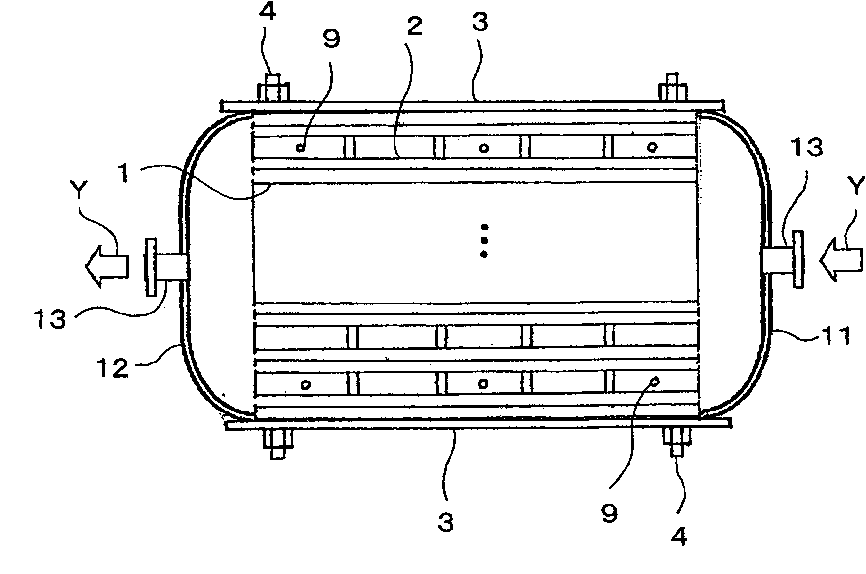
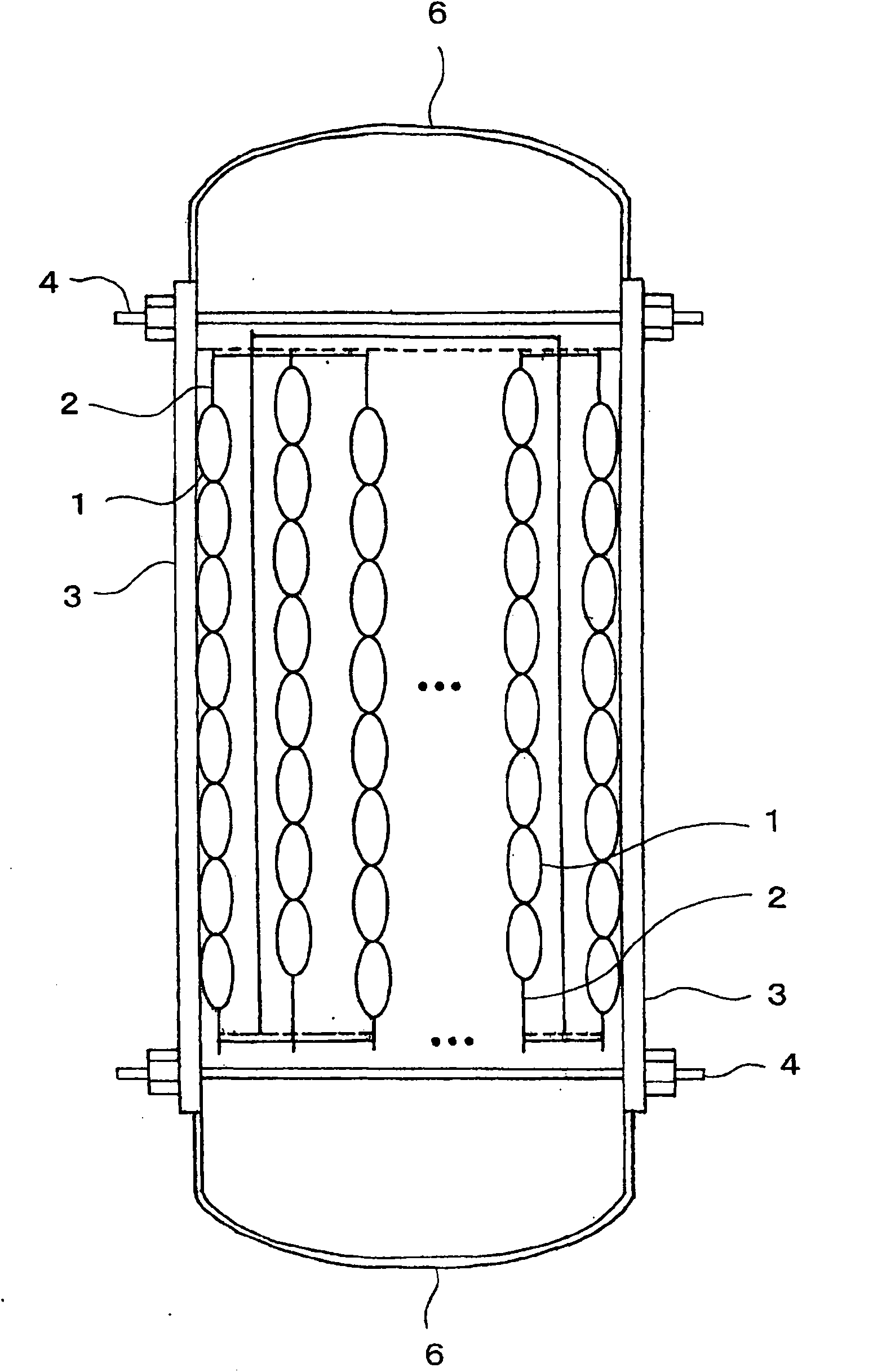
[0250] For example Figure 1 ~ Figure 4 As shown, the first plate reactor has the following components: more than 2 heat transfer plates 2, which are arranged side by side in the above-mentioned reaction vessel, and have heat transfer tubes 1; a pair of clamping plates 3, The pair of clamping plates 3 is at least in contact with the heat transfer plates 2 at both ends of the heat transfer plates 2 along the axis of the heat transfer tube 1, and clamps two or more heat transfer plates 2 in the direction of the heat transfer plates 2. Heat plate 2; two or more holding rods 4, the two or more holding rods 4 connect these clamping plates 3; heat medium supply device 5, the heat medium supply device 5 and the heat transfer tube 1 on the heat transfer plate 2 The two ends are in contact with each other, and heat medium is supplied to the heat transfer tube 1; the gas distribution part 6, the gas distribution part 6 covers the two ends of more than two heat transfer plates 2 in a dir...

no. 2 approach

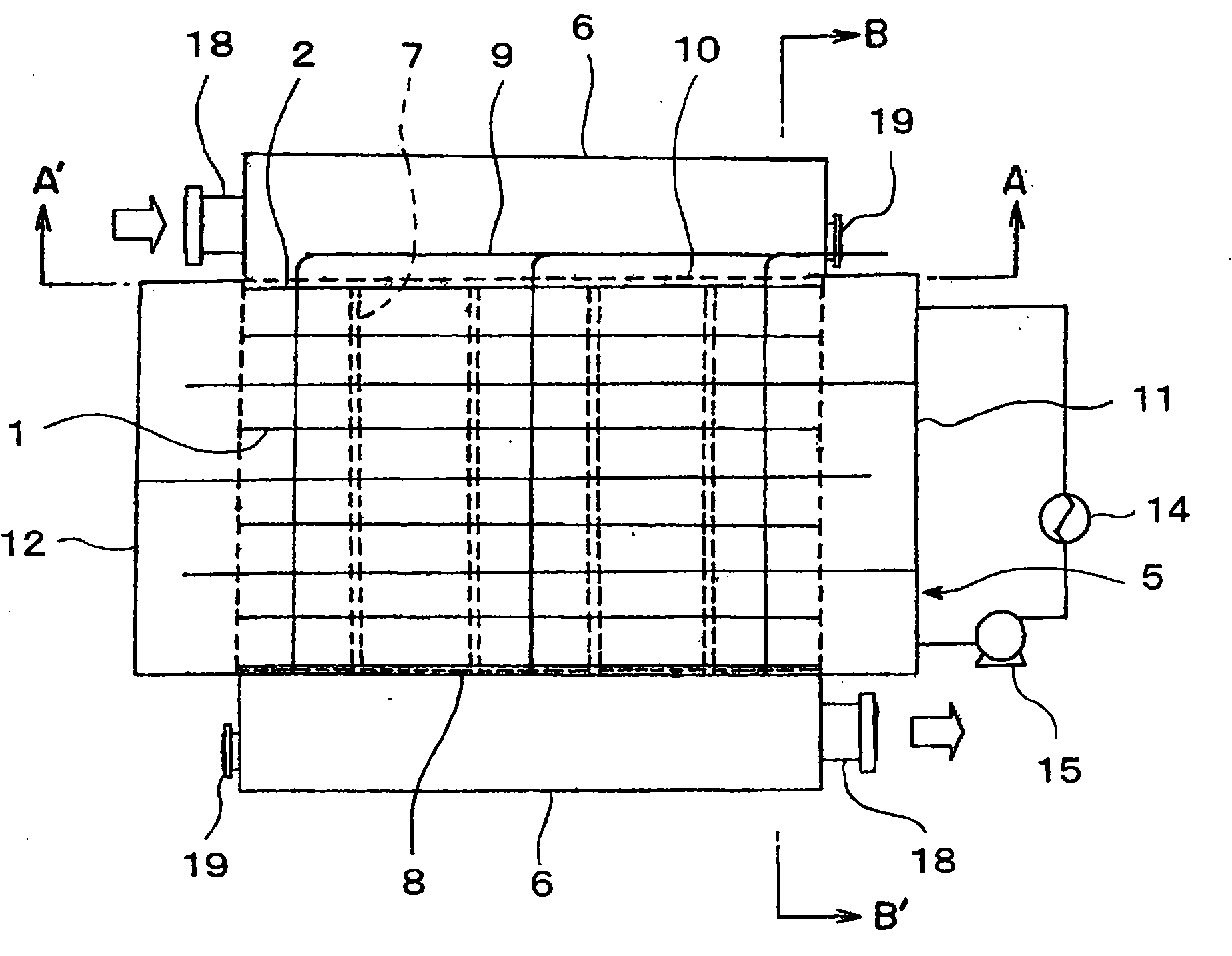
[0328] Such as Figures 13 to 15 As shown, the second plate reactor has: a rectangular shell 44; more than two heat transfer plates 2 that have heat transfer tubes 1 and are arranged opposite to each other in the shell 44; The heat medium housing part 45; the gap between the adjacent heat transfer plates 2 is divided along the ventilation direction in the shell 44 into two or more partitions 7 that fill and hold the catalyst in two or more sections; The perforated plates 10, 46 on the upper and lower parts of the plate 2; the pump 15 for circulating the heat medium body in the heat medium body container 45; and the temperature adjustment device 47 for adjusting the temperature of the circulating heat medium body .

[0329] The casing 44 forms a gas passage with a rectangular cross-sectional shape, and corresponds to the above-mentioned reaction container. In the casing 44, a pair of vent holes 48, 48' opposite to each other are provided at the upper end and the lower end of ...

no. 3 approach

[0350] Such as Figures 23 to 25 As shown, in the second plate reactor, for example, instead of the perforated plate 46, there are two or more vent plugs 8 that are gas-permeable and block the lower end of each section. In addition, there is a plate reaction with the above-mentioned second form. device with the same configuration.

[0351] In the present embodiment, the casing 44 forms an air passage having a rectangular cross-sectional shape, and corresponds to the reaction container described above. The shell 44 has a pair of vents 48, 48' opposite to each other at the upper end and the lower end of the shell 44, and consists of a shell end 49 containing the vent 48, a shell end 49' containing the vent 48', and a heat transfer chamber. Board 2 constitutes the housing body. The housing end portions 49, 49' are each detachably connected to the housing main body. The heat transfer tube 1 is, for example, a tube having an elliptical cross-sectional shape with a major diameter...


PUM

PropertyMeasurementUnit
lengthaaaaaaaaaa
radiusaaaaaaaaaa
sizeaaaaaaaaaa

Abstract

In a plate type reactor, there are provided a technique for preventing the runaway of a reaction in the manufacture of a reaction product and for manufacturing the reaction product in a high productivity, a technique for filling the clearance between adjoining heat transfer plates in the plate type reactor, at least ho ogeneously and easily with a catalyst, and a method for suppressing the pressure loss, the occurrence of a hot spot and the loss of the catalyst even in the run under a high-load condition, thereby to manufacture the reaction product in a high efficiency in the plate type reactor. The reaction product is manufactured by arranging the heat transfer plates of the plate type reactor within a specified range of errors from a designed value, by arranging a plurality of partitions for forming a plurality of compartments in the clearances between the heat transfer plates and along the flow direction of a reaction material, by further arranging a plurality of vent plugs for plugging the bottom portions of the individual partitions removably, and by using a specific reaction material under the condition of a specific quantity of load.

Description

technical field [0001] The present invention relates to a plate reactor used for an exothermic or endothermic reaction involving the use of a catalyst, a method for producing the same, and a method for producing a reaction product by gas-phase contact reaction using the plate reactor. [0002] In addition, the present invention relates to a plate reactor and a method for producing a reaction product by supplying a reaction raw material to a plate reactor filled with a catalyst and reacting the reaction raw material. Background technique [0003] As a reactor used in a gas-phase contact reaction in which a gaseous raw material is reacted in the presence of a solid catalyst to obtain a gaseous reaction product, for example, a multi-tubular reactor in which a catalyst is filled in a reaction tube in a reaction vessel is known. (For example, refer to Patent Document 1) and a plate reactor in which a catalyst is filled in gaps between two or more heat transfer plates in a reactio...

Claims


Application Information

Patent Timeline
Patent Type & Authority Applications(China)
IPC IPC(8): C07C45/35C07C51/21C07C57/05B01J8/02C07C27/14C07C47/22
CPCB01J2219/2497B01J2219/2453B01J19/249B01J2219/2481B01J2219/2471B01J2219/2498C07C45/35C07C51/215C07C51/252B01J2219/2462B01J2219/2459C07C47/22C07C57/04
Inventor 矶谷真治神野公克坂仓康之川谷洋治矢田修平
Owner MITSUBISHI CHEM CORP
Features
  • R&D
  • Intellectual Property
  • Life Sciences
  • Materials
  • Tech Scout
  • Unparalleled Data Quality
  • Higher Quality Content
  • 60% Fewer Hallucinations
Learn More