This helps you quickly interpret patents by identifying the three key elements:
Problems solved by technology
Method used
Benefits of technology
Problems solved by technology
However, in this case, it is necessary to set the sintering temperature low, and as a result, the density is lowered, and there are other problems such as generation of particles, so there is a problem that improvement of target characteristics cannot be expected.
Method used
Image
Click on the blue label to locate the original text in one second.
Reading with bidirectional positioning of images and text.
Examples
Embodiment 1、2
[0098] (Example 1, 2, Comparative Example 1, 2)
[0099] Co-Cr alloy powder and Co and silicon dioxide (SiO 2 ) powder (average particle size 1 ~ 2μm) as sintering raw material powder.
Embodiment 1
[0100] In Example 1, the Co—Cr alloy powder was 75 μm or more and less than 150 μm, and in Example 2 was 20 μm or more and less than 75 μm Co—Cr alloy powder.
[0101] In addition, in Comparative Example 1, Co—Cr alloy powder of less than 20 μm was used, and in Comparative Example 2, Cr powder of less than 20 μm was used instead of Co—Cr alloy powder.
[0102] In addition, the composition of the Co-Cr alloy powder used here contains 40 atomic % or more of Cr.
[0103] Use these powders to have a composition of 77.28Co-14.72Cr-8SiO 2 (mol %) was weighed, and this was mixed for 20 hours with a wet ball mill. Then, this mixed powder was filled into a carbon mold, and sintered by hot pressing (HP) at 1050°C for 2 hours, followed by hot isostatic pressing (HIP) to produce a sintered body, which was then machined. A disk-shaped target with a diameter of 180 mm and a thickness of 7 mm was obtained.
[0104] The relative densities of the targets obtained in this way are all above 9...
Embodiment 3
[0118] (Example 3, Comparative Example 3)
[0119] In Example 3, Co-Cr alloy powder of 75 μm to 150 μm and Co, Pt, and SiO 2 The fine powder (average particle size 1-2μm) is used as the raw material powder for sintering. In addition, in Comparative Example 3, Cr powder of less than 20 μm and Co, Pt, and SiO 2 The fine powder (average particle size 1-2μm) is used as the raw material powder for sintering.
[0120] These powders are respectively composed of 60Co-16Cr-16Pt-8SiO 2 Weigh it in the form of (mol%), mix it with a wet ball mill for 20 hours, fill the mixed powder into a carbon mold, and sinter it at 1050°C for 2 hours by hot pressing (HP), and then perform hot isostatic Press (HIP) processing to manufacture a sintered body, which was then machined to obtain a disc-shaped target with a diameter of 165.1 mm and a thickness of 7 mm. The relative densities of the targets thus obtained were all 97% or more. The results are shown in Table 2.
[0121] Table 2
[0122] ...
PUM
Property
Measurement
Unit
width
aaaaa
aaaaa
particle diameter
aaaaa
aaaaa
length
aaaaa
aaaaa
Abstract
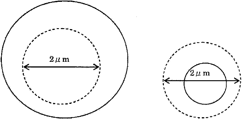
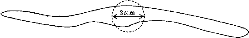
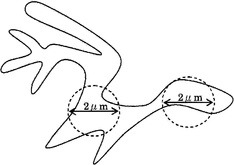
A sputtering target consisting of a nonmagnetic-in-ferromagnetic dispersion type material. This sputtering target comprises a phase (A) composed of both a ferromagnetic Co-Cr alloy material consisting of 5 to 20 at% Cr and the balance Co and nonmagnetic material particles dispersed in the ferromagnetic Co-Cr alloy material and a flaky structure (B) of a Co-Cr alloy phase which is present in the phase (A) and 30 to 100 [mu]m in breadth and 50 to 300 [mu]m in length. The nonmagnetic material particles are each smaller than any imaginary circle formed with a radius of 1[mu]m around an arbitrary point present within the particle, or alternatively the nonmagnetic material particles have each such shape and dimension that at least two contact or intersection points exist between the imaginary circle and the interface between the ferromagnetic material and the nonmagnetic material. The sputtering target attains high PTF (pass through flux) and enables high-speed film formation by a DC magnetron sputtering device. Further, the sputtering target is decreased in the quantity of particles (dust) or nodules generated in sputtering, so that the variation of quality is reduced to bring about improvement in the mass productivity. The sputtering target comprises fine crystal grains and has a high density.
Description
technical field [0001] The present invention relates to a non-magnetic material particle dispersion type ferromagnetic material sputtering target, in particular to a target that can improve PTF (flux leakage) and can be effectively sputtered by using a DC magnetron sputtering device. In addition, when forming a film by sputtering, it can be sputtered stably, an optimum film formation rate can be obtained, arcing during sputtering is small, and the resulting particles (dust) or nodules can be reduced, In addition, it is a non-magnetic material particle-dispersed ferromagnetic material sputtering target with high density and less fluctuation in quality, which can improve mass productivity. Background technique [0002] In the field of magnetic recording, a technique for improving magnetic properties by coexisting a nonmagnetic material in a magnetic thin film has been developed. As an example, there are techniques for improving soft magnetic properties such as magnetic permea...
Claims
Application Information
Patent Timeline
Application Date:The date an application was filed.
Publication Date:The date a patent or application was officially published.
First Publication Date:The earliest publication date of a patent with the same application number.
Issue Date:Publication date of the patent grant document.
PCT Entry Date:The Entry date of PCT National Phase.
Estimated Expiry Date:The statutory expiry date of a patent right according to the Patent Law, and it is the longest term of protection that the patent right can achieve without the termination of the patent right due to other reasons(Term extension factor has been taken into account ).
Invalid Date:Actual expiry date is based on effective date or publication date of legal transaction data of invalid patent.

