Microfluidic device and method

A microfluidic and microfluidic channel technology, applied in mechanical equipment, fluid controllers, chemical instruments and methods, etc., can solve the problems of high power, high inductance, consumption, etc., and achieve high frequency, low inductance, and easy penetration. Effect

Inactive Publication Date: 2011-02-23
KONINK PHILIPS ELECTRONICS NV
View PDF9 Cites 4 Cited by
  • Summary
  • Abstract
  • Description
  • Claims
  • Application Information

AI Technical Summary

Problems solved by technology

These electromagnets are bulky, consume a lot of power, cannot be directly integrated on the substrate and cannot easily oscillate above 10kHz due to their high inductance

Method used


Image

  • Microfluidic device and method
  • Microfluidic device and method
  • Microfluidic device and method

Examples


Embodiment Construction

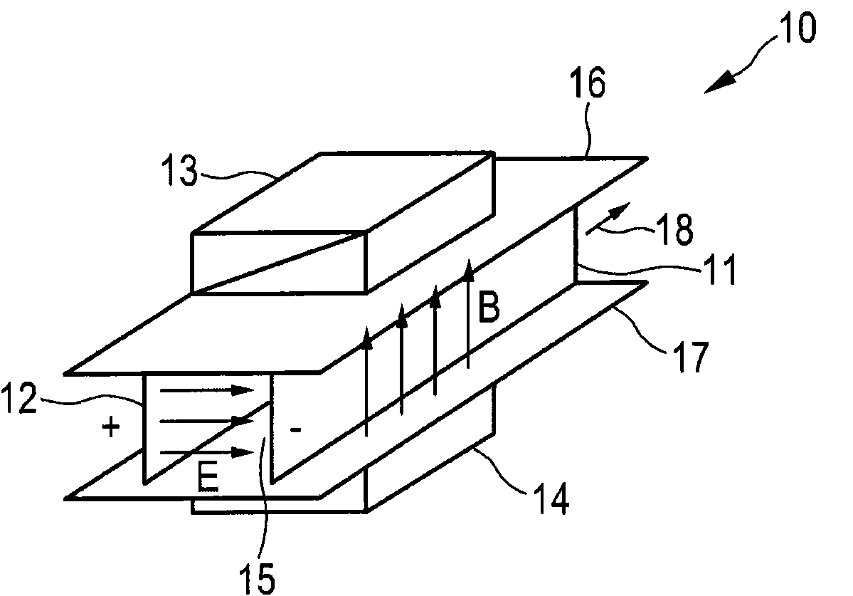
[0042] figure 1 A perspective view of a known MHD unit 10 is schematically shown, with which the magnetohydrodynamic effect will be briefly explained below. This MHD unit 10 comprises two parallel electrode plates 11, 12 for generating an electric field E and external magnets 13, 14 for generating a uniform magnetic field B perpendicular to the direction of the channel 15 formed by the parallel electrode plates 11, 12 and parallel channel plates 16, 17 arranged perpendicularly to the electrode plates 11, 12 are defined. This requires processing electrodes on both sides of the channel 15, or a combination of micromachining (deep trench etching) and photolithography to create a parallel plate configuration.

[0043] The magnetohydrodynamic effect is based on the well-known formula corresponding to the Lorentz force:

[0044] F → = e v → × B →

[0045] ...


PUM


Abstract

The present invention relates to a microfluidic device and a corresponding method for pumping of high conductivity liquids comprising: -a microfluidic channel (26; 80; 101) for containing an electrically conductive liquid, in particular a liquid having a high conductivity, -at least two electric field electrodes (21, 22; 71, 72; 91, 92) for generating electric fields, -at least one magnetic field electrode (21, 22; 75, 76; 93, 94) for generating a magnetic field in a direction substantially perpendicular to said electric fields, -a voltage source (23; 74; 95) for providing electric potentials to said at least two electric field electrodes (21, 22; 71, 72; 91, 92) for generating said electric fields, -a current source (23; 78, 79; 96, 97) for providing an electric current to said at least two magnetic field electrodes (21, 22; 75, 76; 93, 94) for generating said magnetic field, wherein said voltage source (23; 74; 95) and said current source (23; 78, 79; 96, 97) are adapted to simultaneously provide said electric potential and electric current, respectively, to said electrodes to obtain a Lorentz force acting on the high conductivity liquid in the direction (27; 81; 99) of said microfluidic channel (26; 80; 101).

Description

technical field [0001] The present invention relates to a microfluidic device for pumping high conductivity liquids and a corresponding method. Background technique [0002] Handheld medical devices, such as for point-of-care testing, are gaining more and more attention. In these devices, highly conductive liquid samples, such as blood or saliva, must be analyzed for specific biomarkers or biomolecules that indicate an individual's health status. The volume of the liquid sample is small, and the liquid is manipulated within the microfluidic channels and chambers. Said manipulation usually consists of delivering the liquid from the inlet to the measurement location and mixing several liquids. While capillary forces can be exploited in some cases, many applications require active pumping for transport or mixing. [0003] Active pumping mechanisms can generally be divided into mechanical and non-mechanical pumping. The advantage of non-mechanical pumping is that it does not...

Claims


Application Information

Patent Timeline
Patent Type & Authority Applications(China)
IPC IPC(8): H02K44/04
CPCB01L2400/0415H02K44/04B03C1/286B01L2400/043B03C1/023F04B19/006B01L3/50273
Inventor H·范佐恩M·F·吉利斯C·B·克劳斯S·卡塔内奥
Owner KONINK PHILIPS ELECTRONICS NV
Why Eureka
Try Eureka