Tamping wagon photoelectric measurement system and method

A photoelectric measurement and tamping vehicle technology, which is applied in the direction of measuring instruments, measuring devices, and optical devices, can solve the problems of measuring position deviation, reducing measurement accuracy, and poor anti-vibration environment, so as to avoid low measurement accuracy and improve Measurement accuracy, reducing the effect of power wave

Active Publication Date: 2011-03-02
BEIJING LUSTER LIGHTTECH +1
View PDF7 Cites 22 Cited by
  • Summary
  • Abstract
  • Description
  • Claims
  • Application Information

AI Technical Summary

Problems solved by technology

[0004] The invention aims at the problems of low measurement accuracy, easy wear of steel wires, poor anti-vibration environment and difficult maintenance by adopting the traditional steel wire chord measurement method when the tamping car is used for detecting and repairing rail line parameters, while the existing tamping car is equipped with photoelectric The test device is used to detect the parameters of the rail line. Due to the deviation of the measurement position caused by the vibration, the measurement parameters have errors and the measurement accuracy is reduced. A new type of photoelectric measurement system and method for the tamping car is provided, which can better adapt to the tamping car On-site requirements, improve measurement accuracy

Method used


Image

  • Tamping wagon photoelectric measurement system and method
  • Tamping wagon photoelectric measurement system and method
  • Tamping wagon photoelectric measurement system and method

Examples


Embodiment Construction

[0032] The present invention will be described below in conjunction with the accompanying drawings.

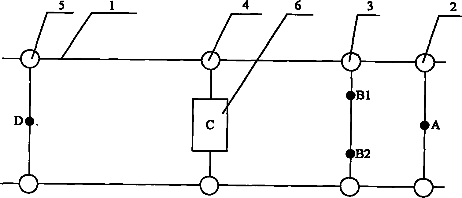
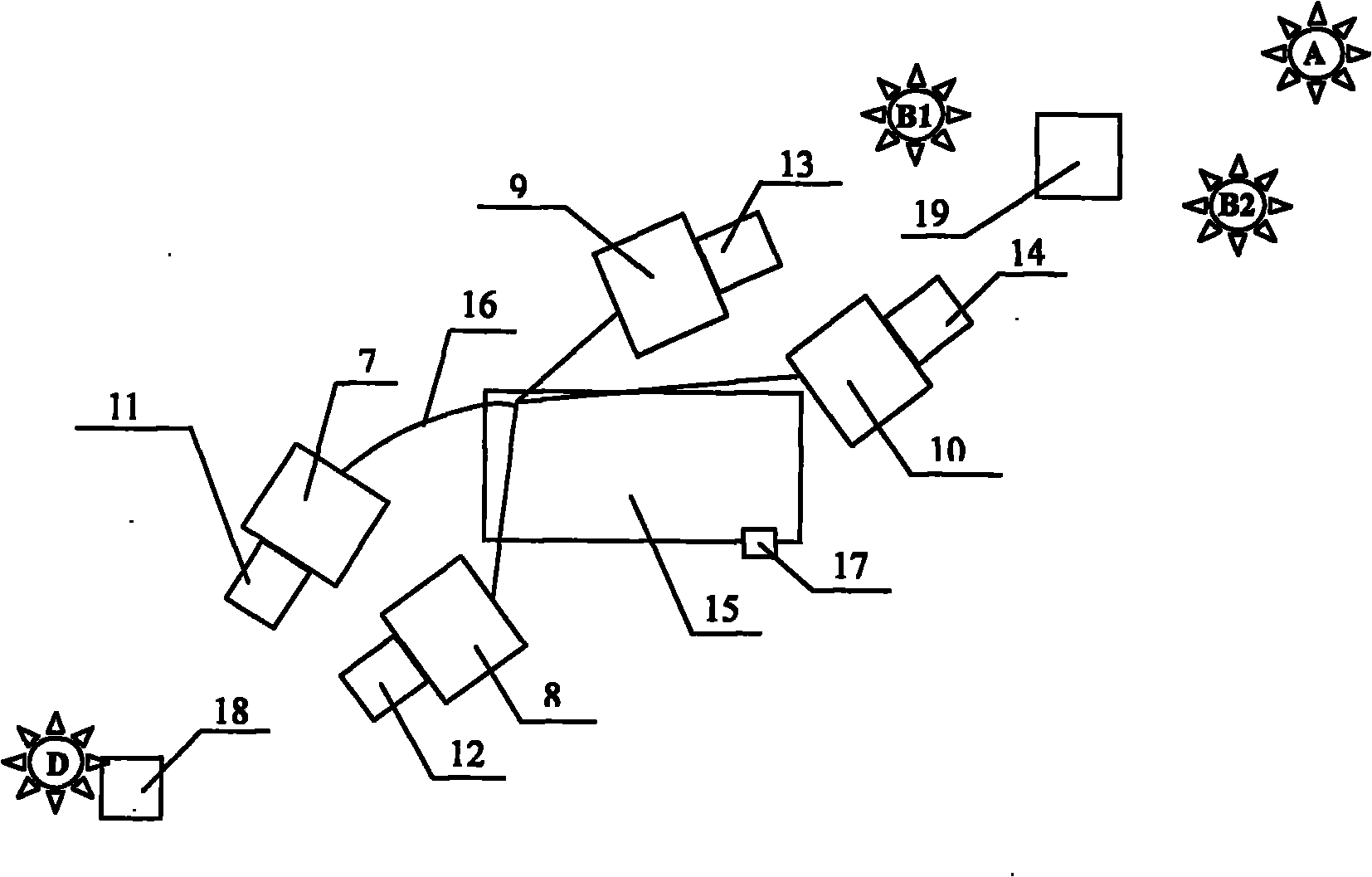
[0033] figure 1 It is a top-view structural schematic diagram of an embodiment of the tamping vehicle photoelectric measurement system of the present invention, including four measuring trolleys that move together with the tamping vehicle on the rail 1, that is, the terminal measuring trolley 2, the rear measuring trolley 3, and the middle measuring trolley 4 And the front measuring trolley 5, four measuring points A, B1, B2, D are set in turn on the measuring trolleys 2, 3, 5, and lighting sources are respectively set at the measuring points, the light source is a remote point light source, and the lighting source provides The high-brightness controllable light source used for measurement is the reference point for measurement. Laser light sources with small light spots and high brightness can be used. The lighting sources A and D are located on the center line of the rail se...


PUM


Abstract

The invention relates to a tamping wagon photoelectric measurement system and a method. The system comprises a front measurement trolley, a middle measurement trolley, a rear measurement trolley, an optical imaging lens, CCD cameras and an illuminating light source, as well as an embedded processing platform and a signal cable, wherein the CCD cameras are connected with the embedded processing platform through the signal cable which contains synchronous signal wires ensuring that four CCD cameras start to shoot images at the same time; the embedded processing platform sends out a signal for the four CCD cameras to sample images synchronously through the signal cable; and the four CCD cameras send data of images which are shot synchronously, correspond to the illuminating light source and are imaged by an optical imaging lens to the embedded processing platform for coupling analysis, and the geometric position of a track circuit is calculated. The tamping wagon photoelectric measurement system can better adapt to the on-site requirement of the tamping wagon, and improves the measurement accuracy.

Description

technical field [0001] The invention relates to a track parameter measuring device in railway maintenance, in particular to a tamping car photoelectric measuring system and method. Background technique [0002] With the six major railway speed increases, the requirements for the quality of railway lines have been greatly improved, and it is no longer possible to rely on manual inspection and maintenance of line quality. It is necessary to use a large-scale road maintenance machine-tamping car to automatically detect and maintain the line. The tamping car is a special vehicle that can simultaneously detect and repair the parameters of the rail line. Its core is the measurement of the parameters of the rail line, and its measurement accuracy is directly related to The performance of the tamping cart and the quality of the tamping job. The method of measuring the parameters of the track by the tamping car usually adopts the traditional steel wire string measurement method. Thi...

Claims


Application Information

Patent Timeline
Patent Type & Authority Applications(China)
IPC IPC(8): E01B35/00E01B35/04E01B35/06E01B35/12E01B27/20G01B11/00G01B11/255
Inventor 张勇金刚卢明舫刘学海
Owner BEIJING LUSTER LIGHTTECH
Why Eureka
Try Eureka