Flexible film microwave strain sensor

A technology of strain sensor and flexible film, applied in the field of strain sensor, can solve the problems of calibration, high cost, calibration, etc., and achieve the effect of solving zero drift and creep

Inactive Publication Date: 2012-05-23
TIANJIN UNIV
View PDF9 Cites 0 Cited by
  • Summary
  • Abstract
  • Description
  • Claims
  • Application Information

AI Technical Summary

Problems solved by technology

However, the fiber-type flexible strain measurement is limited by the difference in its structural arrangement and the characteristics of the signal, especially the optical fiber device requires additional devices such as light source and photoelectric conversion, and the cost is high
In addition, signal drift caused by external environmental factors will also cause problems such as calibration and calibration
[0006] The above patent applications are all realized by time-domain measurement of single-signal input and output, which cannot avoid problems such as drift caused by non-measurement signals such as environmental factors during the measurement process, and corresponding calibration must be carried out for each measurement

Method used


Image

  • Flexible film microwave strain sensor
  • Flexible film microwave strain sensor
  • Flexible film microwave strain sensor

Examples


Embodiment Construction

[0021] The present invention will be described in further detail below in conjunction with the accompanying drawings and embodiments.

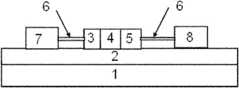
[0022] attached figure 1 It is a structural diagram of a single crystal silicon thin film flexible microwave diode dynamic strain sensor. The substrate includes PET plastic 1 and an adhesive layer 2 to support the main part of the microwave diode dynamic strain sensor. The single crystal silicon thin film flexible microwave diode is on the PET plastic substrate 1 (other types of ordinary plastic or flexible materials can be used as the substrate substrate), and there is a layer of SU8 material layer 2 on the surface of the PET plastic as an adhesive layer. The main part of the work of the thin-film flexible microwave diode strain sensor is a thin-film PIN diode made of doped single-crystal silicon. In the figure, 3, 4, and 5 represent the P-type doped region and the undoped region of the single-crystal silicon thin film, respectively. , and ...


PUM


Abstract

The invention belongs to the technical field of strain measurement, and relates to a flexible film microwave strain sensor which comprises a substrate, a sensor main body, a positive pole and a negative pole, wherein the substrate comprises a plastic layer and an SU8 material layer for bonding a polyethylene terephthalate (PET) plastic layer and the sensor main body; the sensor main body is a monocrystalline silicon film; the film is composed of a P-type doped region, an undoped region and an N-type doped region; the undoped region is positioned between the P-type doped region and the N-type doped region to form a PIN junction; the P-type monocrystalline silicon region is connected with the positive pole; the N-type monocrystalline silicon region is connected with the negative pole; and during measurement, the flexible film microwave strain sensor is fixed on an object to be measured. The flexible film microwave strain sensor can be used for measuring high-frequency dynamic strain, and the accuracy is greatly enhanced.

Description

technical field [0001] The invention belongs to the technical field of strain measurement, and in particular relates to a strain sensor. Background technique [0002] Dynamic strain measurement is generally used to study deformation monitoring with operating frequency of tens of KHz or hundreds of KHz, not only to detect the occurrence of mechanical deformation, but also to detect the change of mechanical deformation in real time. The traditional dynamic strain measurement method basically uses resistance strain gauges to form a measuring bridge, combined with the corresponding peripheral circuits, and adopts frequency modulation to form a dynamic strain measurement system. Among the disclosed patents for dynamic strain measurement, for example, patent CN201096560 discloses a dynamic stress and strain measurement device for stamping dies, including strain rosettes, resistive strain gauges, bridge boxes, dynamic strain gauges, displacement sensors, industrial computers, etc.;...

Claims


Application Information

Patent Timeline
Patent Type & Authority Patents(China)
IPC IPC(8): G01B15/06
Inventor 秦国轩吕辰刚邹强张瑞峰姬中凯马建国
Owner TIANJIN UNIV
Why Eureka
Try Eureka