
Method of manufacturing support for planographic printing plate

Technology of a lithographic printing plate, manufacturing method, applied in the direction of preparation of printing surface, printing, printing process, etc.

Inactive Publication Date: 2012-10-10
FUJIFILM CORP
View PDF4 Cites 0 Cited by
  • Summary
  • Abstract
  • Description
  • Claims
  • Application Information

AI Technical Summary

Problems solved by technology

[0024] That is to say, even if the methods described in the above patent documents are combined separately, it will be as As shown in Figure 8, there may be uneven grains of the aluminum 500 remaining, and a flat portion 503 remains on the convex portion 501 , still can not solve the above problems
In addition, streaky processing unevenness and chatter marks are not sufficiently eliminated, and the problem of uneven image quality cannot be resolved.

Method used


Image

  • Method of manufacturing support for planographic printing plate
  • Method of manufacturing support for planographic printing plate
  • Method of manufacturing support for planographic printing plate

Examples


Embodiment 1

[0379] 1. Manufacture of aluminum plate

[0380] Prepare a melt with an aluminum alloy containing the components (mass %) shown in Table 1, and the balance is composed of Al and unavoidable impurities. After the melt is treated and filtered, the thickness is 500mm and the width is produced by DC casting. 1200mm ingot. After shaving the surface with an average thickness of 10 mm by a face cutter, it was soaked at 550° C. for about 5 hours, cooled to a temperature of 400° C., and rolled into a rolled plate with a thickness of 2.7 mm by a hot rolling machine. Further, after heat-treating at 500° C. with a continuous annealing machine, it was cold-rolled and finished to a thickness of 0.3 mm and a width of 1060 mm to obtain an aluminum plate 1 .

[0381] Table 1

[0382] Aluminum plate Si Fe Cu mn Mg Cr Zn Ti 1 0.080 0.300 0.001 0.001 0.000 0.001 0.003 0.021

[0383] 2. Production of supports for lithographic printin...

Embodiment 1~24 and comparative example 1~9

[0385] The aluminum plate obtained above was subjected to the surface treatment shown below to obtain each support body for lithographic printing plates shown in Table 2.

[0386] Table 2

[0387]

[0388]

[0389] In the surface treatment, the following various treatments (a) to (g) are continuously performed.

[0390] (a) Etching treatment in aqueous alkali solution (first etching treatment)

[0391] An aqueous solution having a caustic soda concentration of 370 g / L, an aluminum ion concentration of 1 g / L, and a temperature of 60° C. was sprayed on the aluminum plate from a spray pipe to perform etching treatment. The amount of etching on the surface of the aluminum plate to be subjected to electrochemical roughening treatment is 3g / m 2 .

[0392] Then, the solution was passed through the pinch rolls, and then washed with water for 5 seconds using a spray pipe having a spray tip that spreads the spray water in a fan shape, and then the liquid was squeezed with the p...

Embodiment 1~24、 comparative example 1~9

[0419] A primer liquid A having the following composition was coated on a lithographic printing plate support, and dried at 80° C. for 15 seconds to form a coating film (intermediate layer) of the components. Coverage of the dried coating film is 15mg / m 2 .

[0420]

[0421] ・The following polymer compound 0.3g

[0422] ·Methanol 100g

[0423] ·Water 1g

[0424]

[0425]Next, in terms of ingredients, it is 0.85g / m after drying 2 Coating solution B1 for an image recording layer having the following composition was applied with a wire bar coater, and dried at 140° C. for 50 seconds.

[0426] Then, according to 0.25g / m after drying 2 Coating solution B2 for the image recording layer with the following composition was applied with a wire bar coater, and dried at 140°C for 1 minute to form a multilayer thermal positive image recording layer to obtain a lithographic printing plate precursor .

[0427]

[0428] N-(4-aminosulfonylphenyl)methacrylamide / acrylonitrile / methy...


PUM

PropertyMeasurementUnit
yield strengthaaaaaaaaaa
lengthaaaaaaaaaa

Abstract

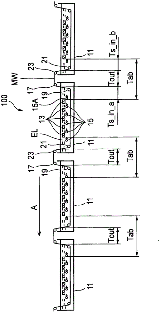
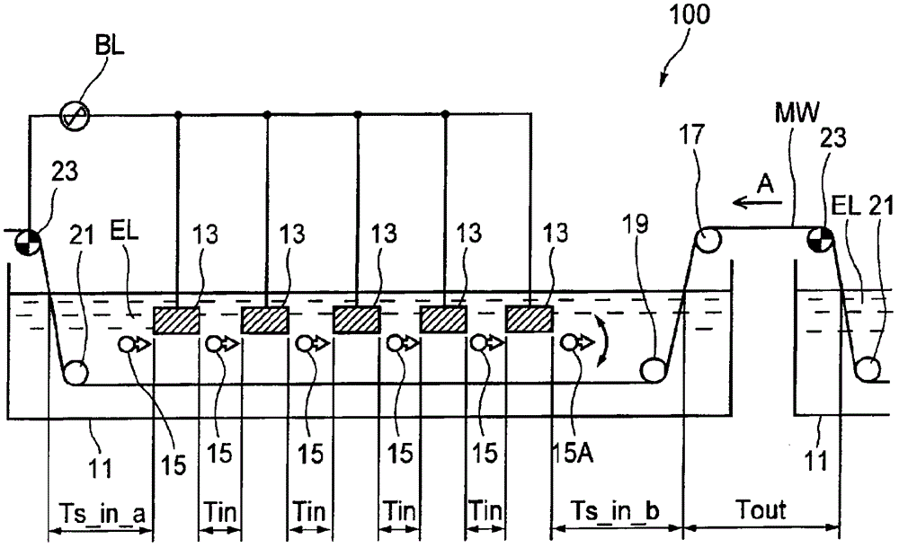
Provided is a method of manufacturing a support for a planographic printing plate, by which the variation in image quality can be reduced and an even tone of sand can be achieved stably. A metal web (MW) formed of aluminum or an aluminum alloy is transferred, being dipped in an electrolyte (EL) of a plurality of electrolyte baths (11) sequentially, and current is supplied between the metal web (MW) and a plurality of electrodes (13) opposite to the metal web (MW) in the electrolyte baths (11) to perform an electrochemical surface roughening treatment on the metal web (MW). During this treatment, the flow rate of the electrolyte (EL) in the electrolyte baths (11) are so set that an average flow rate in the electrolyte baths may be 500 to 4000 mm / sec. and a flow rate distribution of the electrolyte (EL) in the width direction perpendicular to the direction in which the metal web (MW) is transferred in the electrolyte baths (11) may be within + / - 50% of the average flow rate. Letting a region of the transfer path of the metal web which is opposite to a gap between each two adjacent electrodes be a treatment suspension zone between electrodes in the bath, the metal web (MW) is transferred at such a speed that the time (Tin) for the metal web (MW) to pass through one treatment suspension zone between electrodes in the bath may be 0.05 to 1 sec.

Description

technical field [0001] The present invention relates to a method for manufacturing a support body for a lithographic printing plate, which involves sequentially dipping metal webs (metal webs) into the electrolyte solutions of a plurality of electrolytic cells, and controlling the plurality of electrodes arranged opposite to the metal webs in the electrolytic cells and An electric current is supplied between the metal webs, whereby the electrochemical roughening process is continuously performed on the metal webs. Background technique [0002] An aluminum plate is used as a support for printing plates, especially a support for lithographic printing plates, and due to diversification of users, the aluminum plate is also diversified from a plate close to pure aluminum to a plate whose strength is increased by adding manganese. In addition, in order to use such an aluminum plate as a support for a lithographic printing plate, the surface of the support must have moderate adhesi...

Claims


Application Information

Patent Timeline
Patent Type & Authority Patents(China)
IPC IPC(8): C25F3/04B41N1/08B41N3/03C25F7/00
CPCB41N3/034C25F3/04
Inventor 堀田久山崎彻
Owner FUJIFILM CORP
Learn More