Composting device for domestic waste

A domestic garbage and composting technology, applied in the direction of organic fertilizers, climate change adaptation, etc., can solve the problems of decreased utilization rate, slow fermentation and degradation speed, etc., and achieve the effect of increasing utilization rate, increasing fermentation degree, and reducing workload

Inactive Publication Date: 2011-03-09
NINGBO UNIV
View PDF4 Cites 31 Cited by
  • Summary
  • Abstract
  • Description
  • Claims
  • Application Information

AI Technical Summary

Problems solved by technology

For example, the Chinese utility model patent specification whose application date is February 25, 2004 and whose patent number is ZL200420025022.5 discloses a garbage fermentation box, which is a fermentation box composed of a warehouse wall and a warehouse bottom, on which a rotating shaft passes A top cover is installed, and a top cover opening device is installed on the side wall. There are also four lifting holes for lifting on the fermentation box. Door I and door II are respectively installed on the sides of the two ends of the fermentation box. An air supply system and a spray system are installed in the fermentation tank, and a backing plate I and a backing plate II are installed on the inner bottom of the fermentation box, and the backing plate I and the backing plate II are respectively opened with holes of different sizes to facilitate the infiltration of sewage After the top cover is opened, the garbage feed falls on the backing plate I, and after a certain period of fermentation, after the fermentation is completed, it is hoisted into a special dump truck through four lifting holes and fixed, and then the material is discharged. During the process, it can prevent the unpleasant smell from entering the air, but the fermentation speed will be faster at a certain high temperature. In winter, due to the low outside temperature, the fermentation and degradation speed of the garbage in the fermentation tank is very slow, often Make the fermentation tank full of garbage in a short period of time, resulting in a decrease in its utilization

Method used


Image

  • Composting device for domestic waste
  • Composting device for domestic waste

Examples


Embodiment Construction

[0013] The present invention will be further described in detail below in conjunction with the accompanying drawings and embodiments.

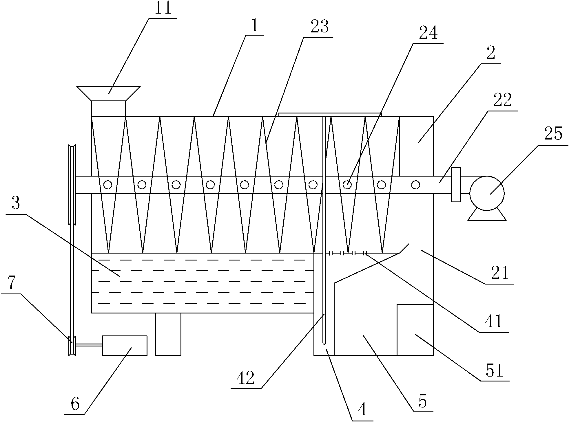
[0014] As shown in the figure, a domestic garbage composting device includes a drive motor 6, a sealed box body 1 and a feed port 11 arranged on the box body 1, and a top cover is sealed on the feed port 11 (not shown in the figure) ), the box body 1 is provided with a composting chamber 2, a water bath 3, a leachate collection box 4 and a secondary composting chamber 5, the feed port 11 communicates with the composting chamber 2, and the composting chamber 2 is provided with a discharge port 21, composting The chamber 2 is provided with a driving shaft 22, on which a helical stirring paddle 23 is fixedly arranged, and the driving motor 6 is connected with the driving shaft 22 through the driving wheel 7, and the driving shaft 22 is provided with an air distribution hole 24, and the end of the driving shaft 22 The fan 25 is connected to the to...


PUM


Abstract

The invention discloses a composting device for domestic waste, which comprises a sealed casing and a feeding inlet provided with the casing. A composting chamber communicating with the feeding inlet is provided inside the casing, and a discharging opening is provided with the composting chamber. A ventilated spiral agitation propeller is provided inside the composting chamber while a water bath below the composting chamber. A heating device is connected with the water bath. The composting device can provide heat for the fermentation of organic domestic waste such as kitchen garbage in the composting chamber to build out the environment benefit for microbe activities, thereby increasing the fermentation speed of organic domestic waste and the utilization rate of heat energy. Meanwhile, solar heating reduces the consumption of conventional energy and is environmental protection. A secondary composting chamber is arranged below the composting chamber, which greatly shortens the longitudinal length of the whole composting apparatus and further saves the occupation area for composting operations, thereby further increasing the composting fermentation degree and reducing workload.

Description

technical field [0001] The invention relates to a domestic waste treatment device, in particular to a domestic waste composting device. Background technique [0002] With the improvement of living standards of urban and rural people, people's health requirements for living environment have also been greatly improved. At present, in the domestic waste disposal industry, the original domestic waste is generally used for composting directly after pretreatment and fermentation for a certain period of time. At present, the main forms of fermentation are open-air and sealed: open-air fermentation will An unpleasant smell is produced, which seriously affects the surrounding environment; sealed fermentation is carried out in a fermentation bin, which is generally composed of four bin walls, a bin top and a bin bottom. For example, the Chinese utility model patent specification whose application date is February 25, 2004 and whose patent number is ZL200420025022.5 discloses a garba...

Claims


Application Information

Patent Timeline
Patent Type & Authority Applications(China)
IPC IPC(8): C05F9/02C05F9/04
CPCY02A40/20
Inventor 李兵董志颖陈宇辉朱建林蔡兆琪
Owner NINGBO UNIV
Why Eureka
Try Eureka