

Integrated immersion quenching device of steel bottle quenching-and-tempering line
A quenching device and production line technology, applied in quenching devices, heat treatment equipment, furnaces, etc., can solve problems such as poor straightness of steel cylinders, poor metallographic structure, crystallization morphology, quenching liquid temperature that cannot meet requirements, and uncertain overall stability factors, etc., to achieve Excellent quenching effect, simple structure, and the effect of reducing the driving load
- Summary
- Abstract
- Description
- Claims
- Application Information
AI Technical Summary
Problems solved by technology
Method used
Image

Examples
Embodiment Construction
[0019] Below in conjunction with accompanying drawing, specific embodiment of the present invention is described in further detail:
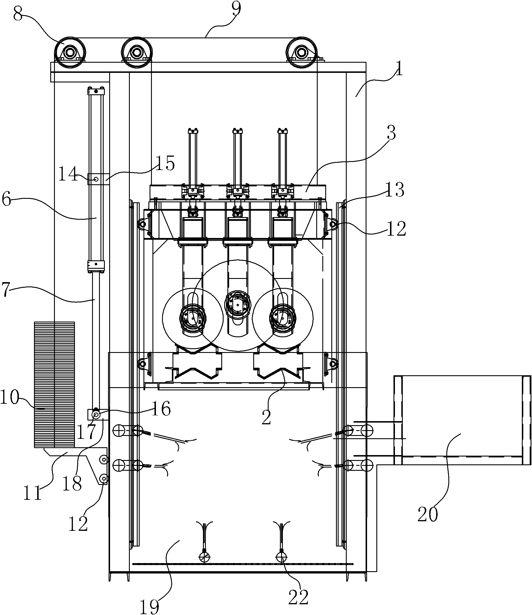
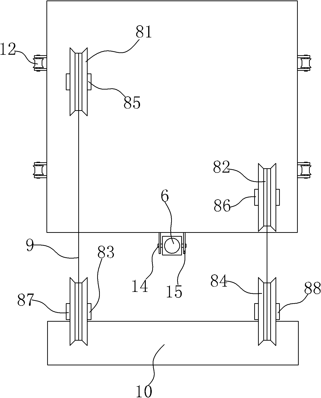
[0020] refer to figure 1 , the quenching frame lifting device, including the main frame 1 and the quenching frame 3 with the steel cylinder clamping mechanism 2, the steel cylinder clamping mechanism 2 includes supporting rollers and pressing mechanisms, etc., a quenching tank is provided under the quenching frame, and the quenching tank includes The main quenching tank 19 and the secondary quenching tank 20 filled with quenching liquid. The side of the quenching frame 3 is provided with a quenching frame roller 4, and the main frame 1 is provided with a first guide rail 5 cooperating with the quenching frame roller 4, which ensures easy assembly and stable operation. The quenching frame roller 4 is arranged, and the quenching frame roller 4 cooperates with the first guide rail clearance of the main frame. The quenching frame 3 is fixedly conn...
PUM
 Abstract
Description
Claims
Application Information