Passive optical network and signal transmission method thereof

A passive optical network and signal transmission technology, applied in the field of communication, can solve problems such as incompatibility, achieve the effect of enhancing compatibility and improving user experience

Active Publication Date: 2011-03-09
ZTE CORP
View PDF5 Cites 36 Cited by
  • Summary
  • Abstract
  • Description
  • Claims
  • Application Information

AI Technical Summary

Problems solved by technology

[0006] The main purpose of the present invention is to provide a signal transmission scheme of a passive optical network, to at least solve the problems caused by point-to-point network or wavelength division multiplexing PON when upgrading the original time-division multiplexing PON in the above-mentioned related technologies. incompatibility issue

Method used


Image

  • Passive optical network and signal transmission method thereof
  • Passive optical network and signal transmission method thereof
  • Passive optical network and signal transmission method thereof

Examples


Embodiment 1

[0062] This embodiment provides a method for enabling the coexistence of the time-division multiplexing passive optical network and the wavelength-division multiplexing passive optical network, thereby solving the application scenario where multi-user high bandwidth and low bandwidth are mixed. The hybrid passive optical network includes: a wavelength division multiplexing coupler, a wavelength selective coupler, an arrayed waveguide grating and a wavelength selective router connected with an optical splitter and a branch fiber. Among them, the wavelength division multiplexing coupler is connected with the time division multiplexing OLT and the wavelength division multiplexing OLT, and is connected with the wavelength selective coupler through the trunk fiber; the wavelength selective coupler is connected with the optical splitter and the arrayed waveguide grating; the arrayed waveguide grating And the optical splitter is respectively connected with the wavelength selection cou...

Embodiment 2

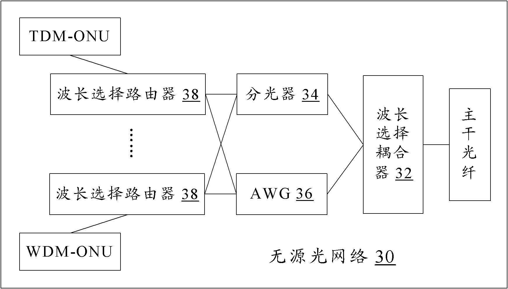
[0074] Taking an example as an example, the composition and structure of the passive optical network in the embodiment of the present invention will be described in detail. Figure 7 It is a schematic structural diagram of a passive optical network where wavelength division multiplexing PON and time division multiplexing PON coexist according to Embodiment 2 of the present invention, as shown in Figure 7 As shown, the passive optical network includes: a wavelength division multiplexing coupler, a wavelength selective coupler, an optical splitter, an arrayed waveguide grating and more than one wavelength selective router connected with the optical splitter. Among them, the wavelength division multiplexing coupler is connected with the time division multiplexing OLT and the wavelength division multiplexing OLT; the wavelength selective coupler is connected through the trunk fiber; the wavelength selective coupler is connected with the optical splitter and the arrayed waveguide g...

Embodiment 3

[0090] In this embodiment, in order to realize the coexistence of the wavelength division multiplexing PON and the time division multiplexing PON, some modifications are made to the passive optical network, and some passive optical functional modules are added.

[0091] First, follow the Figure 7 According to the requirements of the OLT, a wavelength division multiplexing coupler is added at the OLT. Its main function is to couple the downlink signal from the WDM-OLT and the downlink signal from the TDM-OLT (for example, GPON or EPON) into the backbone fiber, and at the same time Separate the upstream signal from the backbone optical fiber, so that the wavelength division multiplexed upstream signal enters the WDM-OLT, and the time division multiplexed upstream signal enters the TDM-OLT.

[0092] Secondly, a wavelength selective coupler is inserted before the splitter. Its main function is to separate the downlink signal of wavelength division multiplexing from the trunk fibe...


PUM


Abstract

The invention discloses a passive optical network (PON) and a signal transmission method thereof. The PON comprises a wavelength selection coupler, an optical splitter, an array waveguide grating (AWG) and a plurality of wavelength selection routers, wherein, the wavelength selection routers couple a downlink signal from a time division multiplexing optical line terminal (TDM-OLT) of the optical splitter and a downlink signal from a wavelength division multiplexing optical line terminal (WDM-OLT) of the AWG and then transmit the coupled signals to branch optical fibers connected with the wavelength selection routers, and transmit an uplink signal in a branch optical fiber connected with a WDM optical network unit (WDM-ONU ) to the AWG and then transmit an uplink signal in a branch optical fiber connected with a TDM-ONU to the optical splitter. The invention enhances network compatibility and improves user experiences.

Description

technical field [0001] The invention relates to the communication field, in particular to a passive optical network and a signal transmission method thereof. Background technique [0002] With the rapid development of network technology and the popularization of network applications, network communication, network shopping and network entertainment have become part of modern people's life. The existing access network copper wire (wired) system can no longer meet this high-speed and broadband demand. The passive optical network is a broadband access technology with broadband, high speed, environmental protection and energy saving, and is the best candidate to replace the existing access network. It is being accepted and deployed by most operators to meet Increasing communication users and demands for faster and better services. [0003] Passive Optical Network (PON for short) is a point-to-multipoint optical fiber access technology, which can be divided into time division m...

Claims


Application Information

Patent Timeline
Patent Type & Authority Applications(China)
IPC IPC(8): H04Q11/00H04J14/02H04L12/56H04B10/2581
CPCH04J14/0282H04J14/0252H04J14/0246H04J14/025H04J14/0247
Inventor 徐继东张德智
Owner ZTE CORP
Why Eureka
Try Eureka