
FRP (fiber reinforced plastic)-steel composite tube concrete column

A technology of concrete columns and composite pipes, which is applied in the direction of columns, pier columns, pillars, etc., can solve the problems of unsatisfactory structural seismic performance, low axial stiffness of FRP pipes, and large lateral deflection, so as to shorten the construction period and save demolition costs. Die process, effect of good axial drawability

Inactive Publication Date: 2011-03-16
DALIAN UNIV OF TECH
View PDF5 Cites 38 Cited by
  • Summary
  • Abstract
  • Description
  • Claims
  • Application Information

AI Technical Summary

Problems solved by technology

However, the FRP material is a linear elastic material. Although its failure mode can be appropriately improved by optimizing the lay-up method, so that the FRP tubular concrete column shows a certain degree of ductile failure, the degree of ductility obtained still cannot meet the requirements of higher and higher requirements. The requirements for the seismic performance of the structure
At the same time, the axial stiffness of the FRP pipe is low, and local buckling may occur due to the self-weight of the concrete during the pouring of concrete, resulting in excessive lateral deflection and local buckling failure

Method used


Image

  • FRP (fiber reinforced plastic)-steel composite tube concrete column
  • FRP (fiber reinforced plastic)-steel composite tube concrete column
  • FRP (fiber reinforced plastic)-steel composite tube concrete column

Examples


Embodiment 1

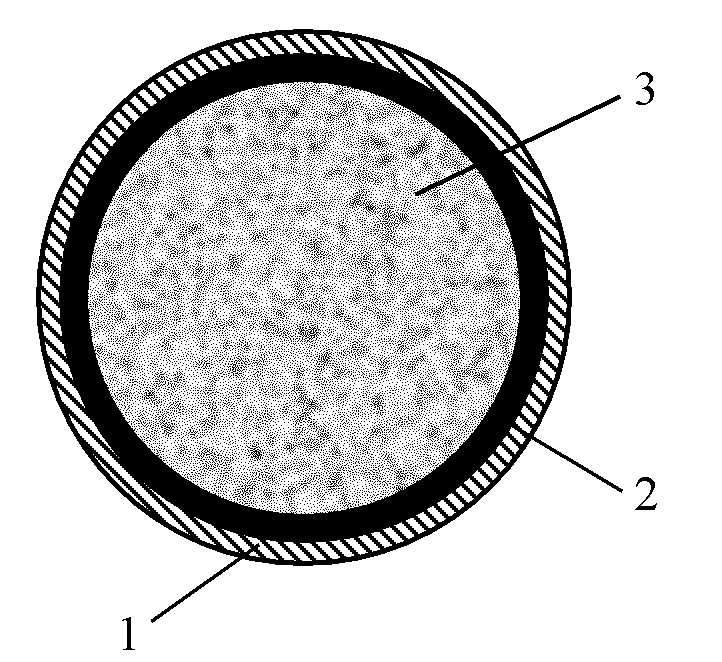
[0022] like figure 1 As shown, the cross-section of the FRP-steel composite pipe concrete column provided by the present invention is a circular structure, mainly composed of a circular FRP-steel composite pipe (circular FRP pipe 1 and circular steel pipe 2) and concrete 3 poured therein . (1) The steel pipe is welded by steel plates, and the two ends of the steel pipe are turned flat on a lathe to ensure the flatness and verticality of the two ends of the steel pipe. The geometric centers coincide and ensure the quality of the weld. (2) The FRP pipe is made by winding process: first, use coarse sandpaper or a grinding machine to derust the outer surface of the steel pipe; secondly, use acetone to clean the polished surface; finally, use the steel pipe as a winding mold and use continuous fiber yarn warp The FRP pipe is made by winding process (at this time, the FRP-steel composite pipe is also made at the same time), the fiber used is glass fiber, carbon fiber, basalt fiber...

Embodiment 2

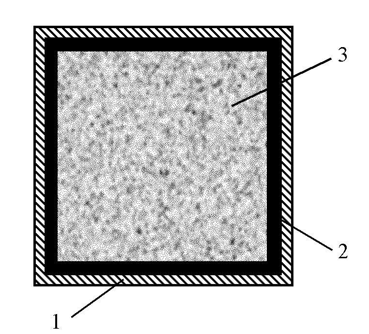
[0024] like figure 2 As shown, the cross-section of this FRP-steel composite pipe concrete column of the present invention is a square structure, mainly composed of square FRP-steel composite pipes (square FRP pipe 1 and square steel pipe 2) and concrete 3 poured therein. The method is the same as in Example 1.

Embodiment 3

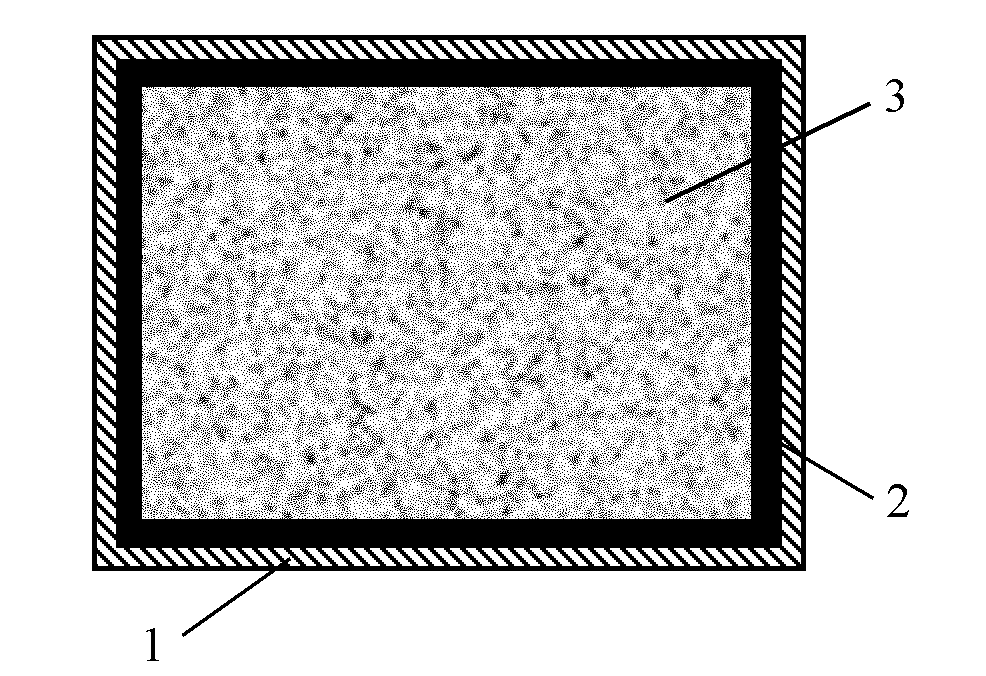
[0026] like image 3 As shown, the cross-section of this FRP-steel composite pipe concrete column of the present invention is a rectangular structure, mainly composed of a rectangular FRP-steel composite pipe (rectangular FRP pipe 1 and rectangular steel pipe 2) and concrete 3 poured into it. The method is the same as in Example 1.


PUM


Abstract

The invention discloses an FRP (fiber reinforced plastic)-steel composite tube concrete column and relates to a civil engineering structural element, the composite tube concrete column consists of an FRP-steel composite tube and concrete filled therein and is characterized in that the FRP-steel composite tube is formed by compounding a steel tube as an inner wall with an FRP tube as an outer wall, the steel tube is formed by welding a steel plate, the FRP tube is prepared by winding continuous fiber yarn on the outer surface of the steel tube, and the solid concrete is poured in the composite tube. The FRP-steel composite tube concrete column can fully play the respective advantages of three composition materials of FRP, steel and concrete and has the characteristics of high bearing capacity, corrosion resistance, excellent aseismic performance and the like, thereby providing a new choice for civil engineering construction.

Description

technical field [0001] The invention belongs to a civil engineering structural member, in particular to a composite column composed of three different materials: FRP pipe, steel pipe and concrete, especially suitable for high-rise buildings, bridge projects and underground projects in harsh environments such as ocean, damp and saline-alkali land and port engineering. Background technique [0002] At present, the CFST column structure has been widely used in high-rise buildings, bridge engineering, underground engineering and port engineering in my country, and has achieved significant economic and social benefits. It can be said that the combination of high-strength concrete and steel pipe under pressure is the most perfect combination, which can be regarded as a model for giving full play to their respective characteristics, and at the same time has excellent ductility characteristics. However, when the concrete-filled steel tube column is subjected to a large load, the cr...

Claims


Application Information

Patent Timeline
Patent Type & Authority Applications(China)
IPC IPC(8): E04C3/34E04B1/30E01D19/02
Inventor 欧进萍李惠王言磊闫昕
Owner DALIAN UNIV OF TECH
Learn More