Pixel driving circuit for active organic light-emitting diode (OLED) display and driving method thereof

A pixel driving circuit and light emitting diode technology, applied in static indicators, instruments, etc., can solve the problems that the threshold voltage cannot achieve uniform display, the peripheral driver chip is difficult to achieve, and the threshold voltage compensation effect is affected, and the number of The effect of improving pixel aperture ratio and saving wiring space

Inactive Publication Date: 2011-03-16
SOUTH CHINA UNIV OF TECH
View PDF5 Cites 88 Cited by
  • Summary
  • Abstract
  • Description
  • Claims
  • Application Information

AI Technical Summary

Problems solved by technology

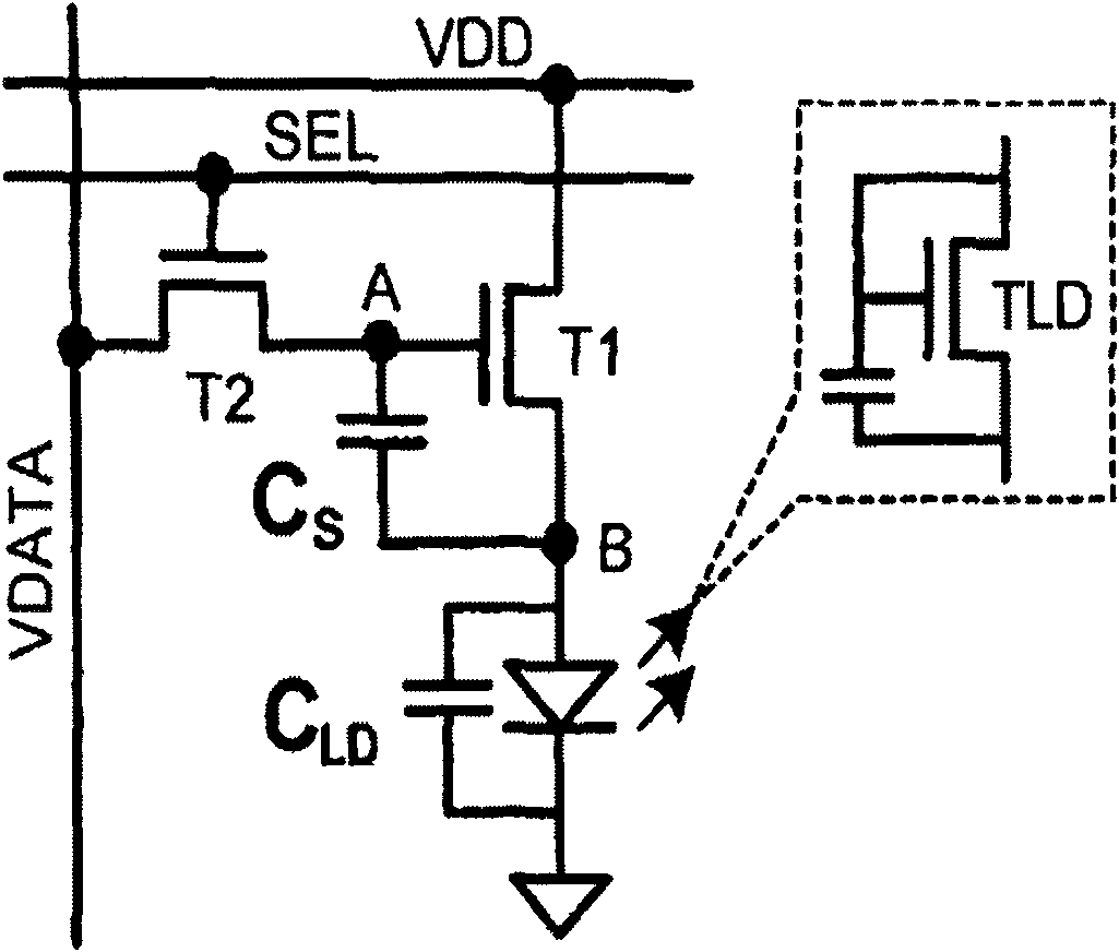
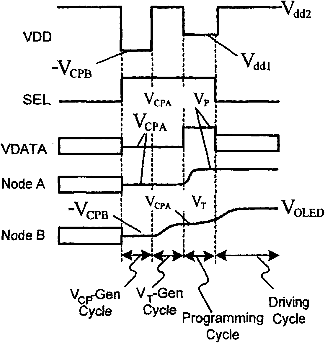
Although the circuit topology is simple, the power line Vdd needs three levels and must meet certain timing requirements. At the same time, it must ensure sufficient current drive capability, and it is difficult to implement the peripheral driver chip.
In addition, in the data voltage writing phase of the pixel circuit, the source voltage of the T1 transistor drifts due to the conduction of the drive transistor T1, and the degree of the drift is related to the magnitude of the written grayscale data voltage, which affects the threshold voltage. compensation effect
In other words, the drift of the source terminal voltage of the T1 tube is equivalent to the drift of the threshold voltage of the T1 tube. In this sense, the pixel circuit fails to fully realize the compensation of the threshold voltage and cannot achieve the purpose of display uniformity.

Method used


Image

  • Pixel driving circuit for active organic light-emitting diode (OLED) display and driving method thereof
  • Pixel driving circuit for active organic light-emitting diode (OLED) display and driving method thereof
  • Pixel driving circuit for active organic light-emitting diode (OLED) display and driving method thereof

Examples


Embodiment

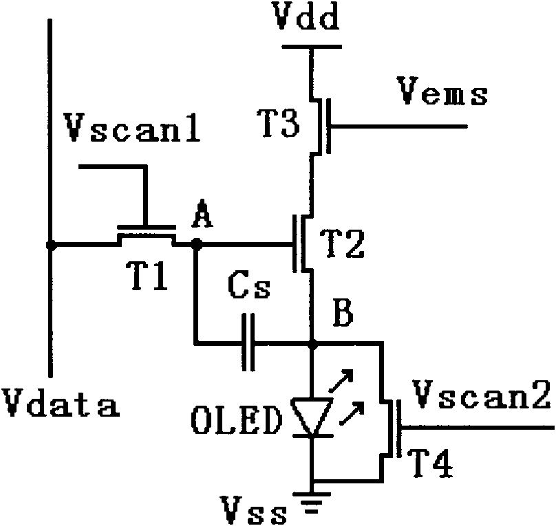
[0026] Such as image 3As shown, the active organic light emitting diode display pixel driving circuit of the present invention includes a first transistor T1, a second transistor T2, a third transistor T3, a fourth transistor T4, a storage capacitor Cs, a first scanning control line Vscan1, a second scanning A control line Vscan2, a light-emitting control line Vems, a power line Vdd, a ground line Vss, a data line Vdata, and an organic light-emitting diode OLED. The aforementioned transistors may be any one of polysilicon thin film transistors, amorphous silicon thin film transistors, zinc oxide-based thin film transistors or organic thin film transistors.

[0027] The drain of the first transistor T1 is connected to the data line Vdata, the gate is connected to the first scanning control line Vscan1, and the source is connected to the A terminal of the storage capacitor Cs, and the first transistor T1 is used for writing the data voltage into the second transistor T2 The ga...


PUM


Abstract

The invention discloses a pixel driving circuit for an active organic light-emitting diode (OLED) display and a driving method thereof. The pixel driving circuit comprises a driving transistor, three switch transistors, a storage capacitor and an OLED, wherein the drain electrode of a first transistor is connected with a data line; the grid electrode of the first transistor is connected with a first scanning control line; the source electrode of the first transistor is connected with the end A of the storage capacitor; the drain electrode of a second transistor is connected with the source electrode of a third transistor; the grid electrode of the second transistor is connected with the end A of the storage capacitor; the source electrode of the second transistor is connected with the drain electrode of a fourth transistor and the end B of the storage capacitor and is grounded through the OLED; the drain electrode of the third transistor is connected with a power wire; the grid electrode of the third transistor is connected with a light-emitting control line; the grid electrode of the fourth transistor is connected with a second scanning control line; and the source electrode of the fourth transistor is grounded. The pixel driving circuit of the invention can effectively compensate the non-uniformity of threshold voltages of the transistors and the degradation of a starting voltage of the OLED so as to realize uniform display screen brightness of the OLED and high contrast ratio.

Description

technical field [0001] The invention relates to a pixel driving technology of a light emitting diode display, in particular to a pixel driving circuit of an active organic light emitting diode display and a driving method thereof. Background technique [0002] Organic light emitting diode display (Organic Light Emitting Diode: OLED) is an all-solid-state process, which has the advantages of small size, independent light emission, large viewing angle, short response time, and low production cost. (PDP) after a very potential flat-panel display. [0003] The active OLED display integrates a thin film transistor (Thin Film Transistor: TFT) and a storage capacitor as a pixel driving circuit in each OLED pixel. Due to the use of TFT to drive each pixel, the OLED is lit during the entire frame period, similar to DC drive, which overcomes the problems caused by the use of pulse signal drive with a small duty cycle in passive drive. The active driving mode reduces the operating cu...

Claims


Application Information

Patent Timeline
Patent Type & Authority Applications(China)
IPC IPC(8): G09G3/32G09G3/3258
Inventor 吴为敬彭俊彪
Owner SOUTH CHINA UNIV OF TECH
Why Eureka
Try Eureka