Optical signal transmitter and method for controlling polarization multiplexed optical signal
A technology for optical signals and transmitters, applied in polarization multiplexing systems, electromagnetic transmitters, multiplexing communications, etc., can solve problems such as optical power difference
- Summary
- Abstract
- Description
- Claims
- Application Information
AI Technical Summary
Problems solved by technology
Method used
Image
Examples
Embodiment approach
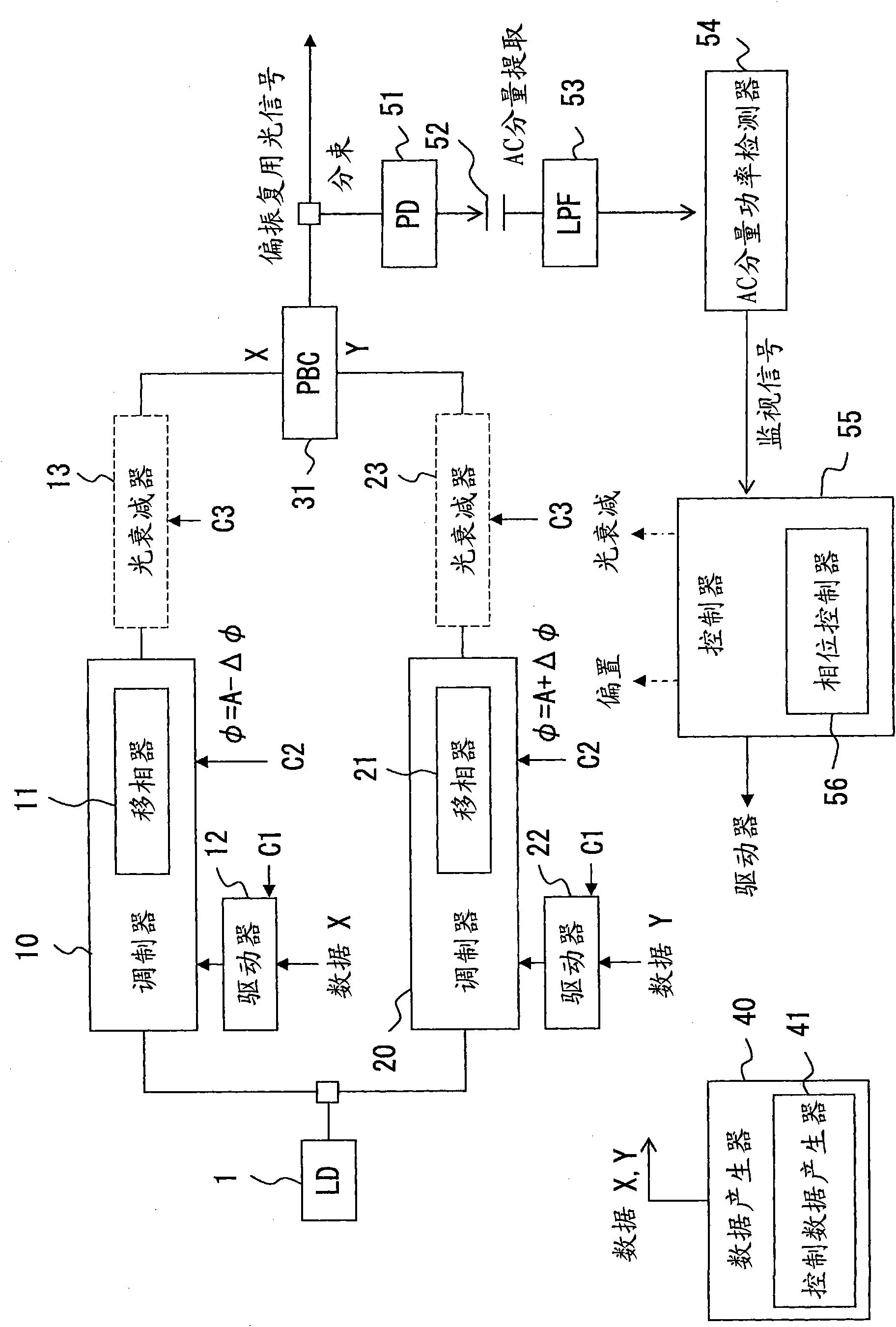
[0144] Figure 19 is a diagram illustrating another structure of an optical signal transmitter. In this example, Figure 19 The second control system of the optical signal transmitter exemplified in is similar to Figure 17 The instantiated structure. However, Figure 19 The illustrated first control system is different from Figure 17 Example of the first control system.
[0145] Figure 19The illustrated optical signal transmitter has a photodetector 131 , a DC component detector 132 , and a controller 133 . In the same manner as the photodetector 51, the photodetector 131 converts the polarization-multiplexed optical signal split by the optical beam splitter into an electrical signal. The DC component detector 132 extracts the DC component of the electric signal obtained by the photodetector 131 . The DC component is detected, for example, by integrating or averaging the input signal from the photodetector 131 . Next, the DC component detector 132 outputs the detec...
PUM
 Abstract
Description
Claims
Application Information
 - R&D
- Intellectual Property
- Life Sciences
- Materials
- Tech Scout
- Unparalleled Data Quality
- Higher Quality Content
- 60% Fewer Hallucinations
Browse by: Latest US Patents, China's latest patents, Technical Efficacy Thesaurus, Application Domain, Technology Topic, Popular Technical Reports.
© 2025 PatSnap. All rights reserved.Legal|Privacy policy|Modern Slavery Act Transparency Statement|Sitemap|About US| Contact US: help@patsnap.com


