
Sump oil dehydration device

A dehydration device and waste oil technology, applied in the direction of electric/magnetic dehydration/emulsification, electric liquid separation, etc., can solve the problems of high oil content in drainage, high current tripping, poor dehydration effect, etc., to reduce oil content in drainage, avoid Disturb, enhance the effect of the effect

Active Publication Date: 2012-06-27
CHINA PETROCHEMICAL CORP +1
View PDF6 Cites 0 Cited by
  • Summary
  • Abstract
  • Description
  • Claims
  • Application Information

AI Technical Summary

Problems solved by technology

[0005] The technical problem to be solved by the present invention is to provide a dehydration device suitable for the recovery of highly water-containing emulsified waste oil, so as to solve the problems of high current tripping, poor dehydration effect, high oil content in drainage water and increased power consumption caused by the treatment of waste oil in the prior art.

Method used


Image

  • Sump oil dehydration device
  • Sump oil dehydration device
  • Sump oil dehydration device

Examples


Embodiment Construction

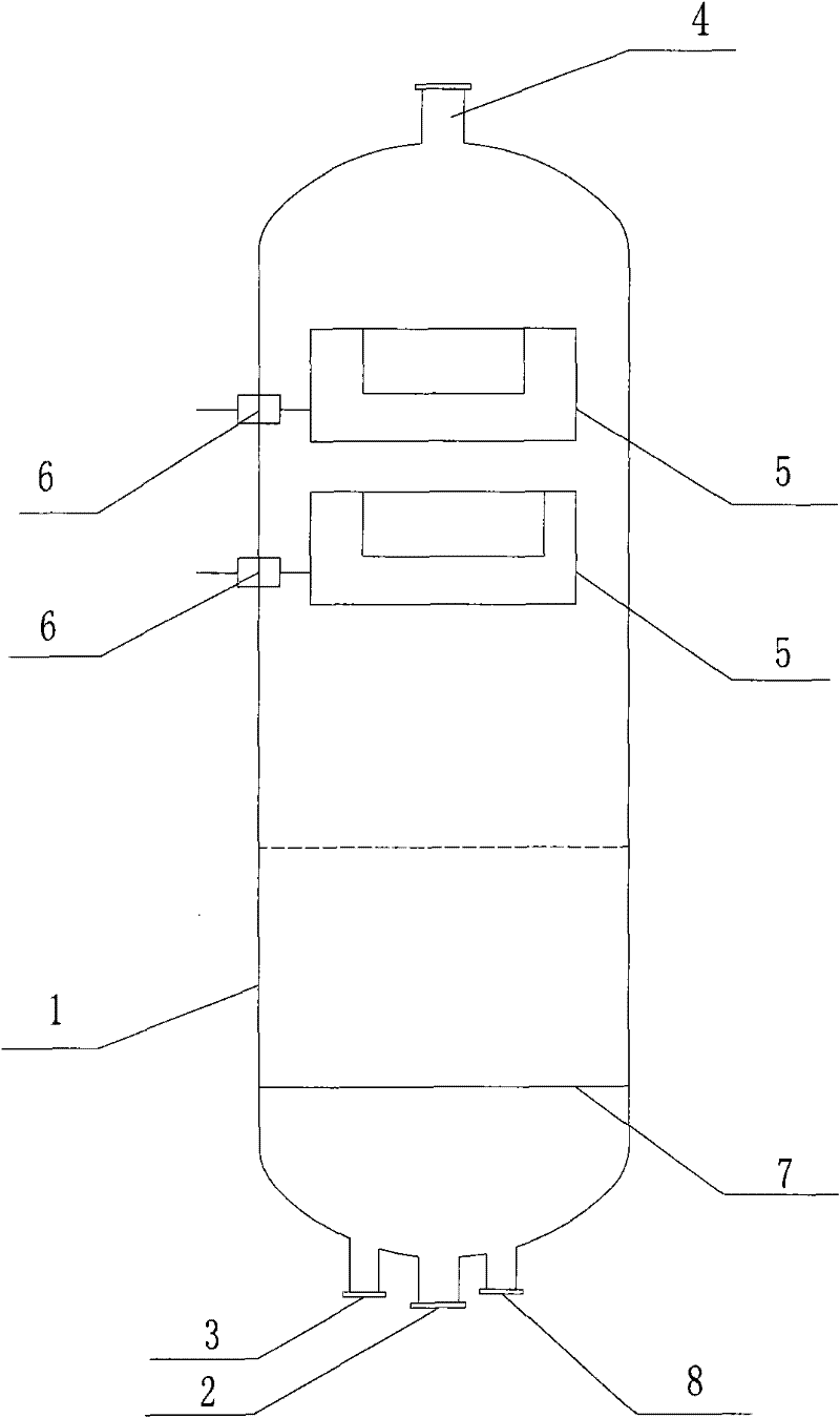
[0017] Such as figure 1 Shown is a kind of waste oil dehydration device of the present invention. It includes a tank body 1, two combined electrodes 5, a high-voltage introduction device 6, a sewage oil inlet pipe 2, a dehydrated sewage oil outlet pipe 4, a drain pipe 3, a sewage oil distributor 7 and a backwash inlet 8; the tank body 1 is a vertical tank , The combined electrode 5 is located in the upper middle part of the tank. The high-voltage introduction device 6 is connected to the combined electrode 5, the dirty oil distributor 7 is located in the middle and lower part of the tank, the dehydrated dirty oil outlet pipe 4 is located at the top of the tank, and the dirty oil inlet pipe 2, drain pipe 3 and backwash inlet 8 are located at the bottom of the tank .

[0018] figure 1 Among them, the dirty oil distributor 7 is set in the clear water layer below the oil-water boundary in the lower part of the tank, and is connected with the dirty oil inlet pipe 2. It is a circ...


PUM


Abstract

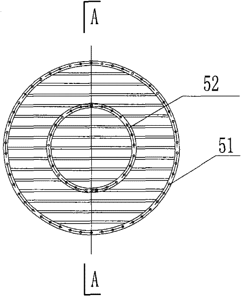
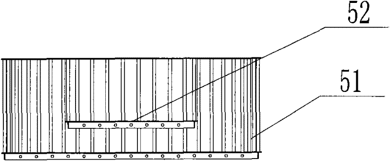
The invention provides a sump oil dehydration device comprising a tank body (1), a combined electrode (5), a high-pressure introducing device (6), a sump oil inlet pipe (2), a dehydration sump oil outlet pipe (4), a drain pipe (3), a sump oil distributor (7) and a backwashing inlet (8). The tank body (1) is a vertical tank, the sump oil distributor (7) is arranged at the mid-lower part in the tank and keeps a certain distance from the tank bottom, the combined electrode (5) is arranged at the mid-upper part in the tank and comprises an inner barrel electrode and an outer barrel electrode which have concentric annular cross sections and even openings, the bottoms of the inner layer and the outer layer and the circular side walls of the inner layer and the outer layer are away at a certain distance, and mutually parallel steel tubes are arranged at equal distances at the bottoms and the circular side walls and are in the structure penetrable for water drops. The dehydration device solves the problems of ultrahigh current tripping, poor dehydration effect, high oil drainage content, electricity increase, and the like caused by sump oil treatment in the prior art and is particularly suitable for the dehydration of emulsified oil and sump oil.

Description

technical field [0001] The invention relates to a waste oil dehydration device, in particular to a waste oil dehydration device suitable for recovery of waste oil in oil fields and refineries. Background technique [0002] Sludge oil containing sediment and impurities is usually produced during crude oil production, gathering and transportation, and refinery production. The water content of these slop oil is usually between 20 and 90% by weight, and it is a complex water-in-oil and oil-in-water Type mixed emulsion is difficult to recycle. Mixing with fresh crude oil for re-refining usually leads to the overall emulsification of crude oil, a decrease in the qualified rate of electrical desalting, and an increase in oil content in drainage, which affects the smooth operation of subsequent devices and has a great impact on product quality. At present, the commonly used electric dehydration / desalination devices are mostly horizontal tanks, the plate structure is horizontal, vert...

Claims


Application Information

Patent Timeline
Patent Type & Authority Patents(China)
IPC IPC(8): B01D17/06C10G33/02
Inventor 崔新安彭松梓段永锋李春贤李兵兵
Owner CHINA PETROCHEMICAL CORP
Learn More