Adjusting method and device for dispersion compensation
A technology of dispersion compensation and adjustment method, applied in the direction of eliminating distortion/dispersion, optical fiber transmission, electrical components, etc., can solve the problem of long adjustment time at the receiving end of the system, achieve low cost and reduce adjustment time
- Summary
- Abstract
- Description
- Claims
- Application Information
AI Technical Summary
Problems solved by technology
Method used
Image

Examples
Embodiment 1
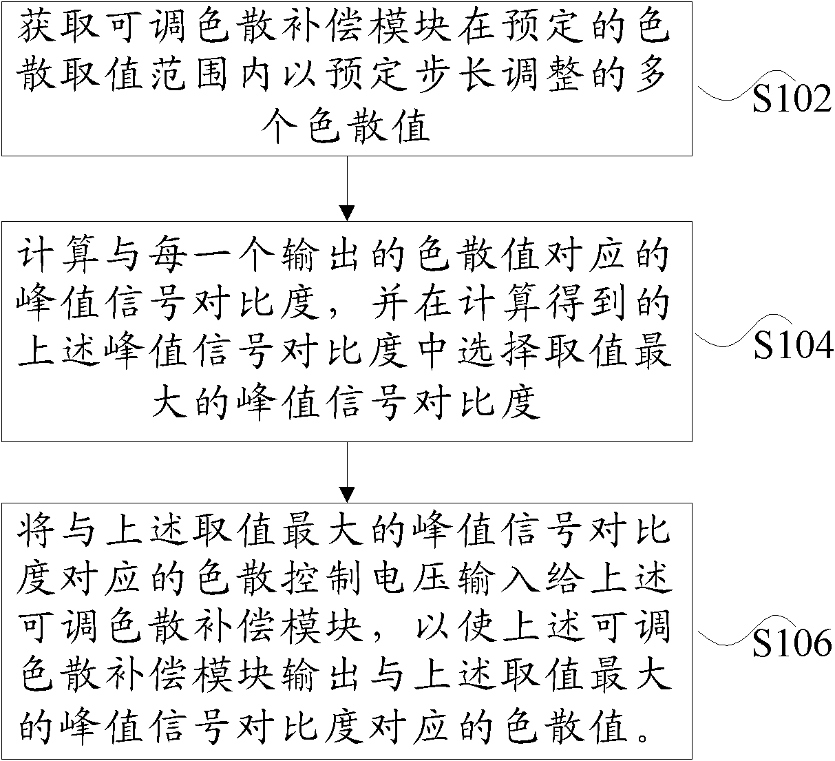
[0027] figure 1 It is a preferred flowchart of the method for adjusting dispersion compensation according to an embodiment of the present invention, which includes the following steps:
[0028] S102: Acquire multiple dispersion values adjusted by a predetermined step length by the tunable dispersion compensation module within a predetermined range of dispersion values;
[0029] S104: Calculate the peak signal contrast corresponding to each output dispersion value, and select the peak signal contrast with the largest value among the calculated peak signal contrasts;
[0030] S106. Input the dispersion control voltage corresponding to the peak signal contrast with the maximum value to the tunable dispersion compensation module, so that the tunable dispersion compensation module outputs a dispersion value corresponding to the peak signal contrast with the maximum value. .
[0031] In this preferred embodiment, the TDC can be automatically adjusted to an appropriate value through closed...
Embodiment 2
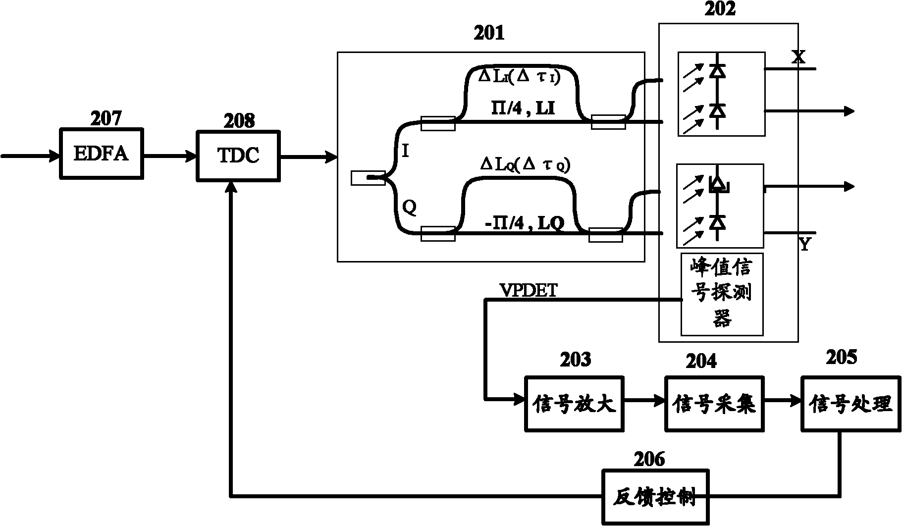
[0038] At the receiving end, the optical signal is first amplified by an erbium-doped fiber amplifier (EDFA), the amplified optical signal is compensated for the residual dispersion of the long fiber with a TDC module, and then the DQPSK demodulator is used to realize the optical phase demodulation. The DLI output The four optical signals enter the double-balanced receiver to complete the photoelectric conversion. The peak signal detector at the receiving end detects the peak of the received optical signal and converts it into a voltage signal for output. The difference between the maximum value and the minimum value of the peak signal is defined as the peak signal contrast. The theoretical calculation shows that when the dispersion value is not appropriate, the peak signal contrast becomes smaller; when the dispersion value is appropriate, the peak signal contrast becomes larger.
[0039] figure 2 It is a schematic diagram of a preferred structure of the DQPSK receiving end acco...
Embodiment 3
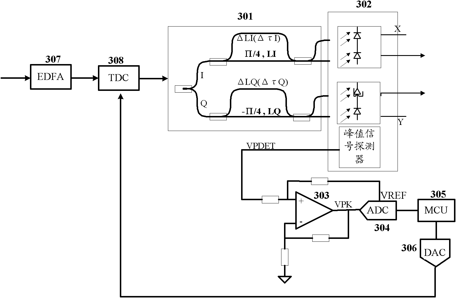
[0045] image 3 It is another preferred structural schematic diagram of the DQPSK receiving end according to an embodiment of the present invention. Such as image 3 As shown, the DQPSK receiving end includes: DQPSK optical demodulator 301, double-balanced receiver 302, signal amplification unit 303 (including operational amplifier circuit), signal acquisition unit 304 (including analog-to-digital converter ADC), signal processing unit 305 ( It includes a microprocessor (MCU), a feedback control unit 306 (including a digital-to-analog converter DAC), an erbium-doped fiber amplifier (EDFA) 307, and a TDC module 308.
[0046] The input optical signal is amplified by EDFA, then adjusted by TDC dispersion, and then decoded by the DQPSK optical demodulator. The decoded optical signal is converted by the double-balanced receiver to complete the photoelectric conversion, and the peak signal detector of the double-balanced receiver is output The voltage VPDET is amplified and translated ...
PUM
 Abstract
Description
Claims
Application Information